- 您現(xiàn)在的位置:買賣IC網(wǎng) > PDF目錄361943 > WSF512K16-39H2M SRAM/EEPROM PDF資料下載
參數(shù)資料
| 型號(hào): | WSF512K16-39H2M |
| 英文描述: | SRAM/EEPROM |
| 中文描述: | 的SRAM / EEPROM的 |
| 文件頁數(shù): | 3/15頁 |
| 文件大?。?/td> | 182K |
| 代理商: | WSF512K16-39H2M |
3
White Electronic Designs Corporation (602) 437-1520 www.whiteedc.com
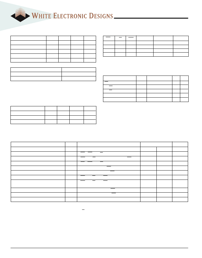
WSF512K16-XXX
ABSOLUTE MAXIMUM RATINGS
DC CHARACTERISTICS
(V
CC
= 5.0V, V
SS
= 0V, T
A
= -55
°
C to +125
°
C)
Parameter
Input Leakage Current
Symbol
I
LI
Conditions
V
CC
= 5.5, V
IN
= GND to V
CC
Min
Max
10
Unit
μ
A
μ
A
mA
mA
V
Output Leakage Current
SRAM Operating Supply Current x 16 Mode
Standby Current
SRAM Output Low Voltage
I
LO
I
CCx16
I
SB
V
OL
FCS = SCS = V
IH
, OE = V
IH,
V
OUT
= GND to V
CC
SCS = V
IL
, OE = V
IH,
f = 5mHz, V
CC
= 5.5, FCS = V
IH
FCS = SCS = V
IH
, OE = V
IH,
f = 5mHz, V
CC
= 5.5
I
OL
= 8mA, V
CC
= 4.5, FCS = V
IH
10
330
45
0.4
SRAM Output High Voltage
Flash V
CC
Active Current for Read (1)
Flash V
CC
Active Current for Program or
Erase (2)
Flash Output Low Voltage
Flash Output High Voltage
V
OH
I
CC1
I
CC2
I
OL
= -4.0mA, V
CC
= 4.5, FCS = V
IH
FCS = V
IL
, OE = V
IH
, SCS = V
IH
FCS = V
IL
, OE = V
IH
, SCS = V
IH
2.4
V
130
150
mA
mA
V
OL
V
OH1
I
OL
= 8.0mA, V
CC
= 4.5, SCS = V
IH
I
OH
= -2.5 mA, V
CC
= 4.5, SCS = V
IH
0.45
V
V
0.85 x V
CC
Flash Low V
CC
Lock Out Voltage
V
LKO
3.2
4.2
V
Parameter
Flash Data Retention
Flash Endurance (write/erase cycles)
20 years
100,000
NOTES:
1. Stresses above the absolute maximum rating may cause permanent damage
to the device. Extended operation at the maximum levels may degrade
performance and affect reliability.
Parameter
Supply Voltage
Input High Voltage
Input Low Voltage
Symbol
V
CC
V
IH
V
IL
Min
4.5
2.2
-0.5
Max
5.5
Unit
V
V
V
V
CC
+ 0.3
+0.8
RECOMMENDED OPERATING CONDITIONS
Parameter
Operating Temperature
Storage Temperature
Signal Voltage Relative to GND
Junction Temperature
Supply Voltage
Symbol
T
A
T
STG
V
G
T
J
V
CC
Min
-55
-65
-0.5
Max
+125
+150
7.0
150
7.0
Unit
°
C
°
C
V
°
C
V
-0.5
SRAM TRUTH TABLE
SCS
H
L
L
L
OE
X
L
H
X
SWE
X
H
H
L
Mode
Standby
Read
Read
Write
Data I/O
High Z
Data Out
High Z
Data In
Power
Standby
Active
Active
Active
CAPACITANCE
(T
A
= +25
°
C)
NOTES:
1. The I
CC
current listed includes both the DC operating current and the frequency dependent component (@ 5 MHz).
The frequency component typically is less than 2 mA/MHz, with OE at V
IH
.
2. I
CC
active while Embedded Algorithm (program or erase) is in progress.
3. DC test conditions: V
IL
= 0.3V, V
IH
= V
CC
- 0.3V
Test
OE Capacitance
F/S WE 1-2 Capacitance
F/S CS 1-2 Capacitance
Data I/O Capacitance
Address Input
Capacitance
This parameter is guaranteed by design but not tested.
Symbol
C
OE
C
WE
C
CS
C
I/O
C
AD
Condition
Max
50
20
20
20
50
Unit
pF
pF
pF
pF
pF
V
IN
= 0V, f = 1.0MHz
V
IN
= 0V, f = 1.0MHz
V
IN
= 0V, f = 1.0MHz
V
IN
= 0V, f = 1.0MHz
V
IN
= 0V, f = 1.0MHz
相關(guān)PDF資料 |
PDF描述 |
|---|---|
| WSF512K16-72G2C | SRAM/EEPROM |
| WSF512K16-72G2I | SRAM/EEPROM |
| WSF512K16-72G2M | SRAM/EEPROM |
| WSF512K16-72H2C | SRAM/EEPROM |
| WSF512K16-72H2I | SRAM/EEPROM |
相關(guān)代理商/技術(shù)參數(shù) |
參數(shù)描述 |
|---|---|
| WSF512K16-39H2MA | 制造商:WEDC 制造商全稱:White Electronic Designs Corporation 功能描述:512KX16 SRAM/FLASH MODULE, SMD 5962-96901 |
| WSF512K16-70G2C | 制造商:WEDC 制造商全稱:White Electronic Designs Corporation 功能描述:512KX16 SRAM/FLASH MODULE, SMD 5962-96901 |
| WSF512K16-70G2CA | 制造商:WEDC 制造商全稱:White Electronic Designs Corporation 功能描述:512KX16 SRAM/FLASH MODULE, SMD 5962-96901 |
| WSF512K16-70G2I | 制造商:WEDC 制造商全稱:White Electronic Designs Corporation 功能描述:512KX16 SRAM/FLASH MODULE, SMD 5962-96901 |
| WSF512K16-70G2IA | 制造商:WEDC 制造商全稱:White Electronic Designs Corporation 功能描述:512KX16 SRAM/FLASH MODULE, SMD 5962-96901 |
發(fā)布緊急采購,3分鐘左右您將得到回復(fù)。