- 您現(xiàn)在的位置:買賣IC網(wǎng) > PDF目錄140380 > WEDPNF8M721V-1015BM (MICROSEMI CORP-PMG MICROELECTRONICS) SPECIALTY MEMORY CIRCUIT, PBGA275 PDF資料下載
參數(shù)資料
| 型號(hào): | WEDPNF8M721V-1015BM |
| 廠商: | MICROSEMI CORP-PMG MICROELECTRONICS |
| 元件分類: | 存儲(chǔ)器 |
| 英文描述: | SPECIALTY MEMORY CIRCUIT, PBGA275 |
| 封裝: | 32 X 25 MM, PLASTIC, BGA-275 |
| 文件頁(yè)數(shù): | 9/42頁(yè) |
| 文件大小: | 1297K |
| 代理商: | WEDPNF8M721V-1015BM |
第1頁(yè)第2頁(yè)第3頁(yè)第4頁(yè)第5頁(yè)第6頁(yè)第7頁(yè)第8頁(yè)當(dāng)前第9頁(yè)第10頁(yè)第11頁(yè)第12頁(yè)第13頁(yè)第14頁(yè)第15頁(yè)第16頁(yè)第17頁(yè)第18頁(yè)第19頁(yè)第20頁(yè)第21頁(yè)第22頁(yè)第23頁(yè)第24頁(yè)第25頁(yè)第26頁(yè)第27頁(yè)第28頁(yè)第29頁(yè)第30頁(yè)第31頁(yè)第32頁(yè)第33頁(yè)第34頁(yè)第35頁(yè)第36頁(yè)第37頁(yè)第38頁(yè)第39頁(yè)第40頁(yè)第41頁(yè)第42頁(yè)
17
White Electronic Designs Corporation (602) 437-1520 www.whiteedc.com
White Electronic Designs
WEDPNF8M721V-XBX
0. Standard read cycle timings and IFCC read specifications
apply. Refer to “Write Operation Status” for more informa-
tion, and to “Flash AC Characteristics” for timing diagrams.
STANDBY MODE
When the system is not reading or writing to the device, it
can place the device in standby mode. In this mode, cur-
rent consumption is greatly reduced, and the outputs are
placed in the high impedance state, independent of the
FOE input.
The device enters the CMOS standby mode when the FCS
and RST pins are both held at Vcc ±0.3V. (Note that this is
a more restricted voltage range than VIH.) If FCS and RST are
held at VIH, but not within Vcc to ±0.3V the device will
be in the standby mode, but the standby current will be
greater. The device requires standard access time (tCE) for
read access when the device is in either of these standby
modes, before it is ready to read data.
If the device is deselected during erasure or programming,
the device draws active current until the operation is com-
pleted.
In the Flash DC Characteristics table, IFCC3 and IFCC4 repre-
sent the standby current specifications.
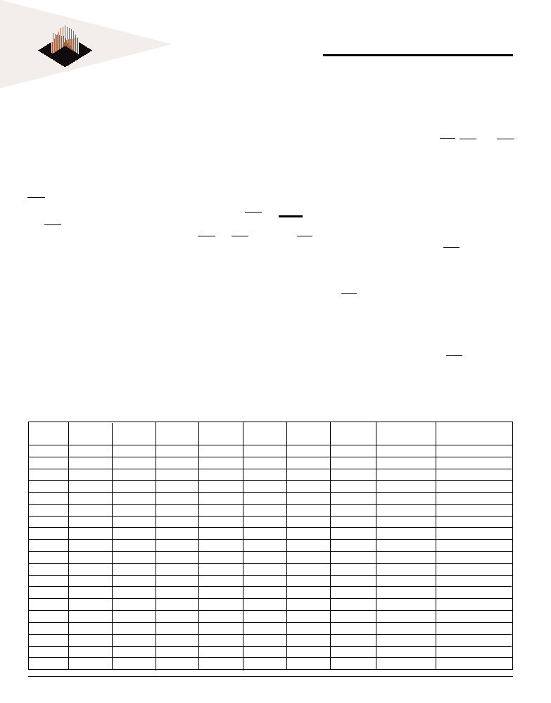
TABLE 5 - BOTTOM BOOT BLOCK SECTOR ADDRESS TABLE
Sector Size
(x8) Address Range
Sector
A18
A17
A16
A15
A14
A13
A12
(Kbytes)
(In hexidecimal)
SA0
0
X
16
00000h-03FFFh
SA1
0
1
0
8
04000h-05FFFh
SA2
0
1
8
06000h-07FFFh
SA3
0
1
X
32
08000h-0FFFFh
SA4
0
1
X
64
10000h-1FFFFh
SA5
0
1
0
X
64
20000h-2FFFFh
SA6
0
1
X
64
30000h-3FFFFh
SA7
0
1
0
X
64
40000h-4FFFFh
SA8
0
1
0
1
X
64
50000h-5FFFFh
SA9
0
1
0
X
64
60000h-6FFFFh
SA10
0
1
X
64
70000h-7FFFFh
SA11
1
0
X
64
80000h-8FFFFh
SA12
1
0
1
X
64
90000h-9FFFFh
SA13
1
0
1
0
X
64
A0000h-AFFFFh
SA14
1
0
1
X
64
B0000h-BFFFFh
SA15
1
0
X
64
C0000h-CFFFFh
SA16
1
0
1
X
64
D0000h-DFFFFh
SA17
1
0
X
64
E0000h-EFFFFh
SA18
1
X
64
F0000h-FFFFFh
AUTOMATIC SLEEP MODE
The automatic sleep mode minimizes Flash device energy
consumption. The device automatically enables this mode
when addresses remain stable for t ACC + 30 ns. The auto-
matic sleep mode is independent of the FCS, FWE, and FOE
control signals. Standard address access timings provide
new data when addresses are changed. While in sleep
mode, output data is latched and always available to the
system. Ifcc5 in the DC Characteristics table represents the
automatic sleep mode current specification.
RST: HARDWARE RESET PIN
The RST pin provides a hardware method of resetting the
device to reading array data. When the RST pin is driven
low for at least a period of tRP or greater the device imme-
diately terminates any operation in progress, tristates all
output pins, and ignores all read/write commands for the
duration of the RST pulse. The device also resets the inter-
nal state machine to reading array data. The operation that
was interrupted should be reinitiated once the device is
ready to accept another command sequence, to ensure
data integrity.
Current is reduced for the duration of the RST pulse. When
相關(guān)PDF資料 |
PDF描述 |
|---|---|
| WF2M32-120G4TI5 | 8M X 8 FLASH 5V PROM MODULE, 120 ns, QMA68 |
| WS512K16-17FLI | 512K X 16 MULTI DEVICE SRAM MODULE, 17 ns, CDFP44 |
| WS512K16-35FLIA | 512K X 16 MULTI DEVICE SRAM MODULE, 35 ns, CDFP44 |
| WE512K16-140G4QA | 512K X 16 EEPROM 5V MODULE, 140 ns, CQFP68 |
| WS512K32NV-15G2UC | 512K X 32 MULTI DEVICE SRAM MODULE, 15 ns, CQFP68 |
相關(guān)代理商/技術(shù)參數(shù) |
參數(shù)描述 |
|---|---|
| WEDPNF8M721V-1210BC | 制造商:未知廠家 制造商全稱:未知廠家 功能描述:8Mx72 Synchronous DRAM + 8Mb Flash Mixed Module Multi-Chip Package |
| WEDPNF8M721V-1210BI | 制造商:未知廠家 制造商全稱:未知廠家 功能描述:8Mx72 Synchronous DRAM + 8Mb Flash Mixed Module Multi-Chip Package |
| WEDPNF8M721V-1210BM | 制造商:未知廠家 制造商全稱:未知廠家 功能描述:8Mx72 Synchronous DRAM + 8Mb Flash Mixed Module Multi-Chip Package |
| WEDPNF8M721V-1212BC | 制造商:未知廠家 制造商全稱:未知廠家 功能描述:8Mx72 Synchronous DRAM + 8Mb Flash Mixed Module Multi-Chip Package |
| WEDPNF8M721V-1212BI | 制造商:未知廠家 制造商全稱:未知廠家 功能描述:8Mx72 Synchronous DRAM + 8Mb Flash Mixed Module Multi-Chip Package |
發(fā)布緊急采購(gòu),3分鐘左右您將得到回復(fù)。