- 您現(xiàn)在的位置:買賣IC網(wǎng) > PDF目錄140345 > WE32K32N-65H1IA (MICROSEMI CORP-PMG MICROELECTRONICS) 32K X 32 EEPROM 5V MODULE, 65 ns, CPGA66 PDF資料下載
參數(shù)資料
| 型號(hào): | WE32K32N-65H1IA |
| 廠商: | MICROSEMI CORP-PMG MICROELECTRONICS |
| 元件分類: | PROM |
| 英文描述: | 32K X 32 EEPROM 5V MODULE, 65 ns, CPGA66 |
| 封裝: | 1.075 X 1.075 INCH, HERMETIC SEALED, CERAMIC, HIP-66 |
| 文件頁數(shù): | 7/13頁 |
| 文件大?。?/td> | 226K |
| 代理商: | WE32K32N-65H1IA |
White Microelectronics Phoenix, AZ (602) 437-1520
10
EEPROM
MODULES
3
WE32K32-XXX
ABSOLUTE MAXIMUM RATINGS
DC CHARACTERISTICS
(VCC = 5.0V, GND = 0V, TA = -55
°C to +125°C)
TRUTH TABLE
NOTE:
Stresses above those listed under "Absolute Maximum Ratings" may cause
permanent damage to the device. This is a stress rating only and functional
operation of the device at these or any other conditions above those indicated in
the operational sections of this specification is not implied. Exposure to
absolute maximum rating conditions for extended periods may affect device
reliability.
RECOMMENDED OPERATING CONDITIONS
CAPACITANCE
(TA = 25
° C)
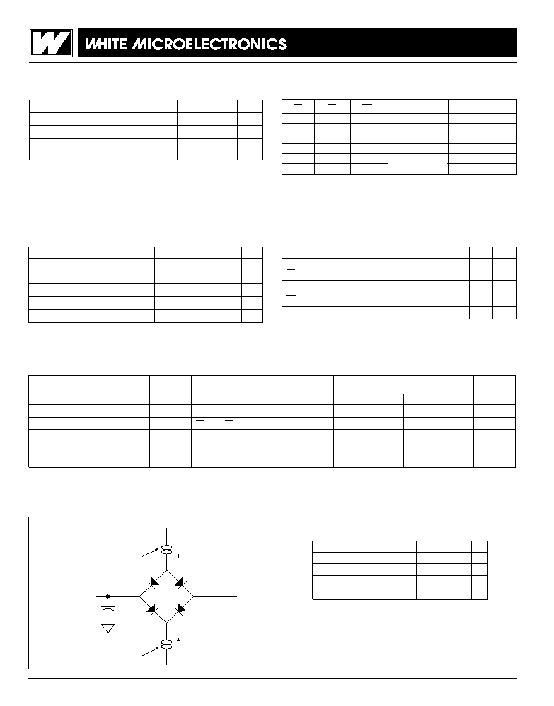
FIG. 3
AC TEST CIRCUIT
AC TEST CONDITIONS
I
Current Source
D.U.T.
C
= 50 pf
eff
I
OL
V
≈ 1.5V
(Bipolar Supply)
Z
Current Source
OH
NOTES:
VZ is programmable from -2V to +7V.
IOL & IOH programmable from 0 to 16mA.
Tester Impedance Z0 = 75
.
VZ is typically the midpoint of VOH and VOL.
IOL & IOH are adjusted to simulate a typical resistive load circuit.
ATE tester includes jig capacitance.
CS
OE
WE
Mode
Data I/O
H
X
Standby
High Z
L
H
Read
Data Out
L
H
L
Write
Data In
X
H
X
Out Disable
High Z/Data Out
X
H
Write
X
L
X
Inhibit
Parameter
Symbol
Unit
Operating Temperature
TA
-55 to +125
°C
Storage Temperature
TSTG
-65 to +150
°C
Voltage on any Pin with respect
-1.0 to +7.0
V
to GND
Parameter
Symbol
Min
Max
Unit
Supply Voltage
VCC
4.5
5.5
V
Input High Voltage
VIH
2.0
VCC + 0.3
V
Input Low Voltage
VIL
-0.5
+0.8
V
Operating Temp. (Mil.)
TA
-55
+125
°C
Operating Temp. (Ind.)
TA
-40
+85
°C
Parameter
Symbol
Condition
Max
Unit
Address Input Capacitance
CAD
VIN = 0V, f = 1.0MHz
50
pF
OE Capacitance
COE
CS1-4 Capacitance
CCS
VIN = 0V, f = 1.0MHz
20
pF
WE1-4 Capacitance
CWE
VIN = 0V, f = 1.0MHz
20
pF
Data I/O Capacitance
CI/O
VIN = 0V, f = 1.0MHz
20
pF
This parameter is guaranteed by design but not tested.
Parameter
Symbol
Conditions
Units
Min
Max
Input Leakage Current
ILI
VCC = 5.5, VIN = GND to VCC
10
A
Output Leakage Current
ILO x 32
CS = VIH, OE = VIH, VOUT = GND to VCC
10
A
Operating Supply Current x 32 Mode
ICC x 32
CS = VIL, OE = VIH, f = 5MHz
320
mA
Standby Current
ISB
CS = VIH, OE = VIH, f = 5MHz
100
mA
Output Low Voltage
VOL
IOL = 2.1mA, VCC = 4.5V
0.4
V
Output High Voltage
VOH
IOH = -400
A, VCC = 4.5V
2.4
V
NOTE: DC test conditions: VIH = VCC -0.3V, VIL = 0.3V
Parameter
Typ
Unit
Input Pulse Levels
VIL = 0, VIH = 3.0
V
Input Rise and Fall
5
ns
Input and Output Reference Level
1.5
V
Output Timing Reference Level
1.5
V
相關(guān)PDF資料 |
PDF描述 |
|---|---|
| WED3DG6418V7D2 | 16M X 64 SYNCHRONOUS DRAM MODULE, DMA168 |
| WF2M32-150HM5 | 2M X 32 FLASH 5V PROM MODULE, 150 ns, CPGA66 |
| WF2M32-90G2UQ5 | 2M X 32 FLASH 5V PROM MODULE, 90 ns, CQFP68 |
| WF2M32I-150G2UM5 | 2M X 32 FLASH 5V PROM MODULE, 150 ns, CQFP68 |
| WF2M32I-150HM5 | 2M X 32 FLASH 5V PROM MODULE, 150 ns, CPGA66 |
相關(guān)代理商/技術(shù)參數(shù) |
參數(shù)描述 |
|---|---|
| WE32K32N-80H1C | 制造商:未知廠家 制造商全稱:未知廠家 功能描述:EEPROM |
| WE32K32N-80H1CA | 制造商:未知廠家 制造商全稱:未知廠家 功能描述:EEPROM |
| WE32K32N-80H1I | 制造商:未知廠家 制造商全稱:未知廠家 功能描述:EEPROM |
| WE32K32N-80H1IA | 制造商:未知廠家 制造商全稱:未知廠家 功能描述:EEPROM |
| WE32K32N-80H1M | 制造商:未知廠家 制造商全稱:未知廠家 功能描述:EEPROM |
發(fā)布緊急采購(gòu),3分鐘左右您將得到回復(fù)。