- 您現(xiàn)在的位置:買賣IC網(wǎng) > PDF目錄202172 > V59C1512164QCF3I (PROMOS TECHNOLOGIES INC) 32M X 16 DDR DRAM, 0.45 ns, PBGA84 PDF資料下載
參數(shù)資料
| 型號(hào): | V59C1512164QCF3I |
| 廠商: | PROMOS TECHNOLOGIES INC |
| 元件分類: | DRAM |
| 英文描述: | 32M X 16 DDR DRAM, 0.45 ns, PBGA84 |
| 封裝: | ROHS COMPLIANT, MO-207, FBGA-84 |
| 文件頁數(shù): | 1/76頁 |
| 文件大小: | 1192K |
| 代理商: | V59C1512164QCF3I |
當(dāng)前第1頁第2頁第3頁第4頁第5頁第6頁第7頁第8頁第9頁第10頁第11頁第12頁第13頁第14頁第15頁第16頁第17頁第18頁第19頁第20頁第21頁第22頁第23頁第24頁第25頁第26頁第27頁第28頁第29頁第30頁第31頁第32頁第33頁第34頁第35頁第36頁第37頁第38頁第39頁第40頁第41頁第42頁第43頁第44頁第45頁第46頁第47頁第48頁第49頁第50頁第51頁第52頁第53頁第54頁第55頁第56頁第57頁第58頁第59頁第60頁第61頁第62頁第63頁第64頁第65頁第66頁第67頁第68頁第69頁第70頁第71頁第72頁第73頁第74頁第75頁第76頁
1
V59C1512(404/804/164)QC*I
512 Mbit DDR2 SDRAM, INDUSTRIAL TEMPERATURE
4 BANKS X 32Mbit X 4 (404)
4 BANKS X 16Mbit X 8 (804)
4 BANKS X 8Mbit X 16 (164)
V59C1512(404/804/164)QC*I Rev.1.1 April 2008
5
37
3
25A
25
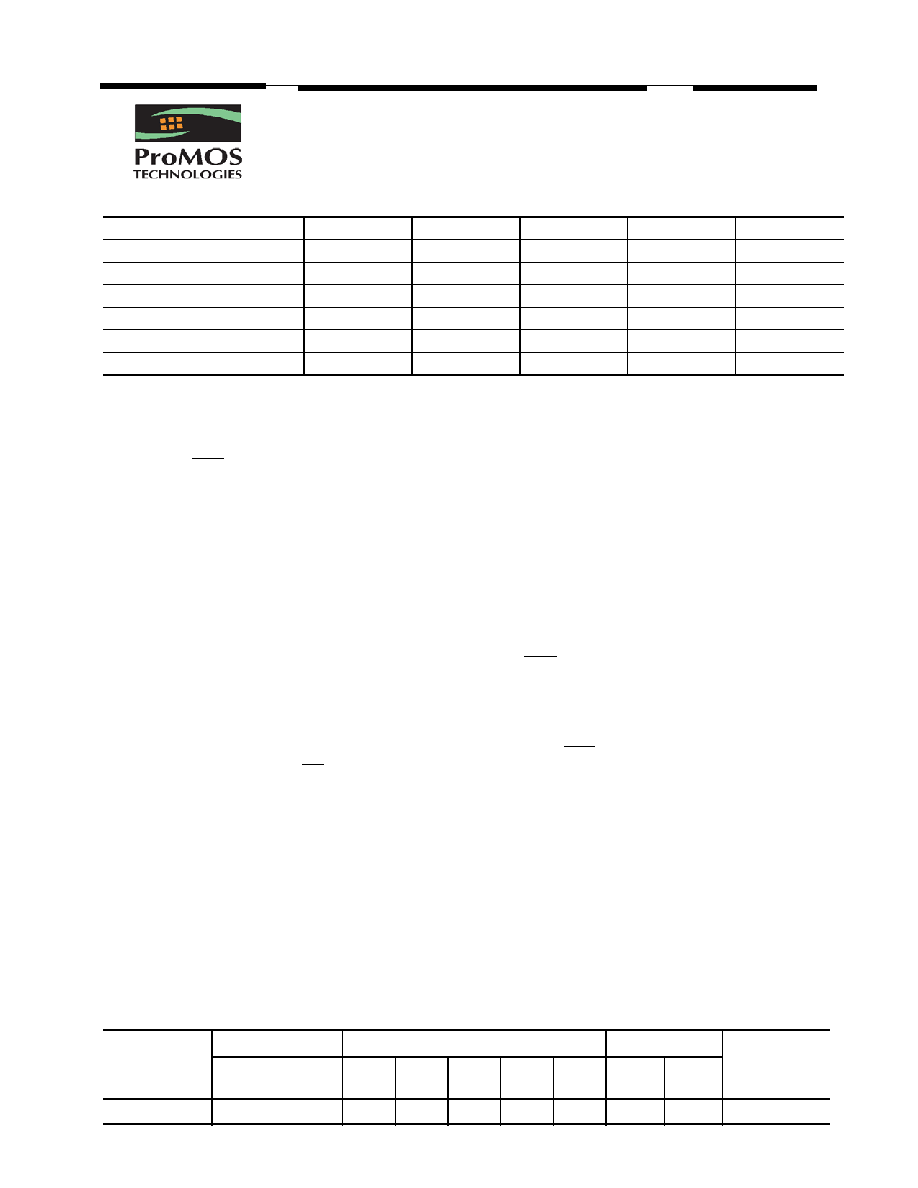
DDR2-400
DDR2-533
DDR2-667
DDR2-800
Clock Cycle Time (tCK3)
5ns
Clock Cycle Time (tCK4)
5ns
3.75ns
Clock Cycle Time (tCK5)
5ns
3.75ns
3ns
2.5ns
Clock Cycle Time (tCK6)
5ns
3.75ns
3ns
2.5ns
System Frequency (fCK max)
200 MHz
266 MHz
333 MHz
400 MHz
Features
■ High speed data transfer rates with system frequency
up to 400MHz
■ Posted CAS
■ Programmable CAS Latency: 3, 4, 5 and 6
■ Programmable Additive Latency:0, 1, 2, 3, 4 and 5
■ Write Latency=Read Latency-1
■ Programmable Wrap Sequence: Sequential
or Interleave
■ Programmable Burst Length: 4 and 8
Automatic and Controlled Precharge Command
■ Power Down Mode
■ Auto Refresh and Self Refresh
■ Refresh Interval: 7.8 us (8192 cycles/64 ms)
■ OCD (Off-Chip Driver Impendance Adjustment)
■ ODT (On-Die Termination)
■ Weak Strength Data-Output Driver Option
■ Bidirectional differential Data Strobe (Single-ended
data-strobe is an optional feature)
■ On-Chip DLL aligns DQ and DQs transitions with CK
transitions
■ Differential clock inputs CK and CK
■ JEDEC Power Supply 1.8V ± 0.1V
■ VDDQ=1.8V ± 0.1V
■ Available in 60-ball FBGA for x4 and x8 component or
84 ball FBGA for x16 component
■ PASR Partial Array Self Refresh
■ All inputs & outputs are compatible with SSTL_18 in-
terface
■ tRAS lockout supported
■ Read Data Strobe supported (x8 only)
■ Internal four bank operations with single pulsed RAS
■ Industrial Temperature (TA): -40C to +85C
Description
The V59C1512(404/804/164)QC*I is a four bank DDR
DRAM organized as 4 banks x 32Mbit x 4 (404), 4 banks x
16Mbit x 8 (804), or 4 banks x 8Mbit x 16 (164). The
V59C1512(404/804/164)QC*I achieves high speed data
transfer rates by employing a chip architecture that
prefetches multiple bits and then synchronizes the output
data to a system clock.
The chip is designed to comply with the following key
DDR2 SDRAM features:(1) posted CAS with additive la-
tency, (2)write latency=read latency-1, (3)Off-chip Driv-
er(OCD) impedance adjustment, (4) On Die Termination.
All of the control, address, circuits are synchronized
with the positive edge of an externally supplied clock. I/O
s are synchronized with a pair of bidirectional strobes
(DQS, DQS) in a source synchronous fashion.
Operating the four memory banks in an interleaved
fashion allows random access operation to occur at a
higher rate than is possible with standard DRAMs. A se-
quential and gapless data rate is possible depending on
burst length, CAS latency and speed grade of the device.
Available Speed Grade:
-5 (DDR2-400) @ CL 3-3-3
-37 (DDR2-533) @ CL 4-4-4
-3 (DDR2-667) @ CL 5-5-5
-25A (DDR2-800) @ CL 6-6-6
-25 (DDR2-800) @ CL 5-5-5
Device Usage Chart
Operating
Temperature
Range
Package Outline
CK Cycle Time (ns)
Power
Temperature
Mark
60 ball FBGA
84 ball FBGA
-5
-37
-3
-25A
-25
Std.
L
-40°C to +85°C
I
相關(guān)PDF資料 |
PDF描述 |
|---|---|
| V59C1G01168QBLJ-25I | DDR DRAM, PBGA84 |
| V59C1G01408QAUP25A | 256M X 4 DDR DRAM, PBGA68 |
| V59C1512164QALJ25AH | 32M X 16 DDR DRAM, PBGA92 |
| V59C1512164QALP37I | 32M X 16 DDR DRAM, PBGA92 |
| V59C1512164QAUJ5I | 32M X 16 DDR DRAM, PBGA92 |
相關(guān)代理商/技術(shù)參數(shù) |
參數(shù)描述 |
|---|---|
| V59C1512164QDJ25 | 制造商:ProMOS 功能描述:32M*16 DDRII, 1.8V, BGA, 400MHz, Green Part 制造商:ProMOS Technologies INC. 功能描述:32M*16 DDRII, 1.8V, BGA, 400MHz, Green Part |
| V59C1512164QDJ25A | 制造商:ProMOS 功能描述:32M*16 DDRII, 1.8V, BGA, 800MHz, Green Part, CL6 制造商:ProMOS Technologies INC. 功能描述:32M*16 DDRII, 1.8V, BGA, 800MHz, Green Part, CL6 |
| V59C1512164QDJ25I | 制造商:ProMOS 功能描述:32M*16 DDRII, 1.8V, BGA, 333MHz, Green Part, 制造商:ProMOS Technologies INC. 功能描述:32M*16 DDRII, 1.8V, BGA, 333MHz, Green Part, |
| V59C1512164QDJ3 | 制造商:ProMOS 功能描述:32M*16 DDRII, 1.8V, BGA, 333MHz, Green Part 制造商:ProMOS Technologies INC. 功能描述:32M*16 DDRII, 1.8V, BGA, 333MHz, Green Part |
| V59C1512164QDJ3I | 制造商:ProMOS 功能描述:32M*16 DDRII, 1.8V, BGA, 333MHz, Green Part, 制造商:ProMOS Technologies INC. 功能描述:32M*16 DDRII, 1.8V, BGA, 333MHz, Green Part, |
發(fā)布緊急采購(gòu),3分鐘左右您將得到回復(fù)。