- 您現(xiàn)在的位置:買賣IC網(wǎng) > PDF目錄300082 > V53C8128HK45 (MOSEL-VITELIC) 128K X 8 EDO DRAM, 45 ns, PDSO24 PDF資料下載
參數(shù)資料
| 型號: | V53C8128HK45 |
| 廠商: | MOSEL-VITELIC |
| 元件分類: | DRAM |
| 英文描述: | 128K X 8 EDO DRAM, 45 ns, PDSO24 |
| 封裝: | 0.300 INCH, SOJ-26/24 |
| 文件頁數(shù): | 8/20頁 |
| 文件大?。?/td> | 222K |
| 代理商: | V53C8128HK45 |
16
MOSEL-VITELIC
V53C8128H
V53C8128H Rev. 1.1 November 1997
Extended Data Out Page Mode
The V53C8128H offers fast access within a row.
Unlike ordinary fast page mode DRAM, the
V53C8128H output remains active and valid even
after
CAS goes high and it will stay valid for 5ns after
CAS changes low.
The feature allows the
V53C8128H to
CAS cycle faster than ordinary page
mode DRAM since the cycle time be short as data
access time.
The outputs are disabled at the tHZ time after
RAS
and
CAS are high. The tHZ time is referenced from
rising edge of
RAS or CAS whichever occurs last. In
addition, high on
OE input and activation of the write-
cycle will also disable the outputs.
The following equation can be used to calculate the
maximum data rate:
256
Data Rate =
tRC + 255 x tPC
Data Output Operation
The V53C8128H Input/Output is controlled by
OE, CAS, WE and RAS. A RAS low transition
enables the transfer of data to and from the
selected row address in the Memory Array. A
RAS
high transition disables data transfer and latches
the output data if the output is enabled. After a
memory cycle is initiated with a
RAS low transition,
a
CAS low transition or CAS low level enables the
internal I/O path. A
CAS high transition or a CAS
high level disables the I/O path and the output driver
if it is enabled. A
CAS low transition while RAS is
high has no effect on the I/O data path or on the
output drivers. The output drivers, when otherwise
enabled, can be disabled by holding
OE high. The
OE signal has no effect on any data stored in the
output latches. A
WE low level can also disable the
output drivers when
CAS is low. During a Write
cycle, if
WE goes low at a time in relationship to
CAS that would normally cause the outputs to be
active, it is necessary to use
OE to disable the
output drivers prior to the
WE low transition to allow
Data In Setup Time (tDS) to be satisfied.
Power-On
After application of the VCC supply, an initial
pause of 200
s is required followed by a minimum
of 8 initialization cycles (any combination of cycles
containing a
RAS clock). Eight initialization cycles
are required after extended periods of bias without
clocks (greater than the Refresh Interval).
During Power-On, the VCC current requirement of
the V53C8128H is dependent on the input levels of
RAS and CAS. If RAS is low during Power-On, the
device will go into an active cycle and ICC will exhibit
current transients. It is recommended that
RAS and
CAS track with V
CC or be held at a valid VIH during
Power-On to avoid current surges.
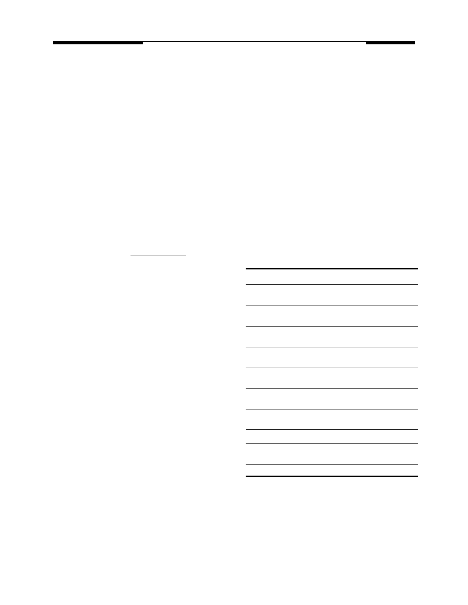
Table 1. V53C8128H Data Output
Operation for Various Cycle Types
Cycle Type
I/O State
Read Cycles
Data from Addressed
Memory Cell
CAS-Controlled Write
High-Z
Cycle (Early Write)
WE-Controlled Write
OE Controlled. High
Cycle (Late Write)
OE = High-Z I/Os
Read-Modify-Write
Data from Addressed
Cycles
Memory Cell
Fast Page Mode
Data from Addressed
Read
Memory Cell
Fast Page Mode Write
High-Z
Cycle (Early Write)
Fast Page Mode Read-
Data from Addressed
Modify-Write Cycle
Memory Cell
RAS-only Refresh
High-Z
CAS-before-RAS
Data remains as in
Refresh Cycle
previous cycle
CAS-only Cycles
High-Z
相關PDF資料 |
PDF描述 |
|---|---|
| V53C8256LK60 | x8 Fast Page Mode DRAM |
| V53C8256LP60 | x8 Fast Page Mode DRAM |
| V53C8256LT60 | x8 Fast Page Mode DRAM |
| V53C8257HK-45 | x8 Burst EDO Page Mode DRAM |
| V53C8257HK-50 | x8 Burst EDO Page Mode DRAM |
相關代理商/技術參數(shù) |
參數(shù)描述 |
|---|---|
| V53C8256HP45 | 制造商:Mosel Vitelic Corporation 功能描述: |
| V53C864K10L | 制造商:VITELIC 功能描述: |
| V53C864K80L | 制造商:VITELIC 功能描述: |
| V5-4/RK 4-0.3/0.3/0.3 | 制造商:TURCK Inc 功能描述:Cordset, Splitter, M12 Female Straight x 3, 4 Wire, 4m, PVC, Yellow |
| V-5410EK | 制造商:Honeywell Sensing and Control 功能描述:V Basics |
發(fā)布緊急采購,3分鐘左右您將得到回復。