- 您現(xiàn)在的位置:買賣IC網(wǎng) > PDF目錄382720 > UDA1326PS (NXP Semiconductors N.V.) USB AUDIO-CODEC(通用串行總線音頻編解碼器) PDF資料下載
參數(shù)資料
| 型號(hào): | UDA1326PS |
| 廠商: | NXP Semiconductors N.V. |
| 元件分類: | Codec |
| 英文描述: | USB AUDIO-CODEC(通用串行總線音頻編解碼器) |
| 中文描述: | USB音頻編解碼器(通用串行總線音頻編解碼器) |
| 文件頁數(shù): | 10/43頁 |
| 文件大小: | 678K |
| 代理商: | UDA1326PS |
第1頁第2頁第3頁第4頁第5頁第6頁第7頁第8頁第9頁當(dāng)前第10頁第11頁第12頁第13頁第14頁第15頁第16頁第17頁第18頁第19頁第20頁第21頁第22頁第23頁第24頁第25頁第26頁第27頁第28頁第29頁第30頁第31頁第32頁第33頁第34頁第35頁第36頁第37頁第38頁第39頁第40頁第41頁第42頁第43頁
Philips
Semiconductors, Inc.
USB-CODEC UDA1325PS
Technical Report
DML98022
* HID inputs 1& 2:
As you will see, both HID inputs are implemented on the application board. The respective switches are defined
as S2 and S3. Depending on the definition of each switch, theoretically you should be able to use these switches
for different purposes. These functions are defined in the
Universal Serial Bus HID Usage Tables
document.
In version 1.0 of this document -page 60-, you will see many functions defined that are supported by Win98.
In this case, only Audio related functions are interesting for us. Therefore, page 62 has some interesting
functions like Volume control, mute, bass etc. that you could define or test.
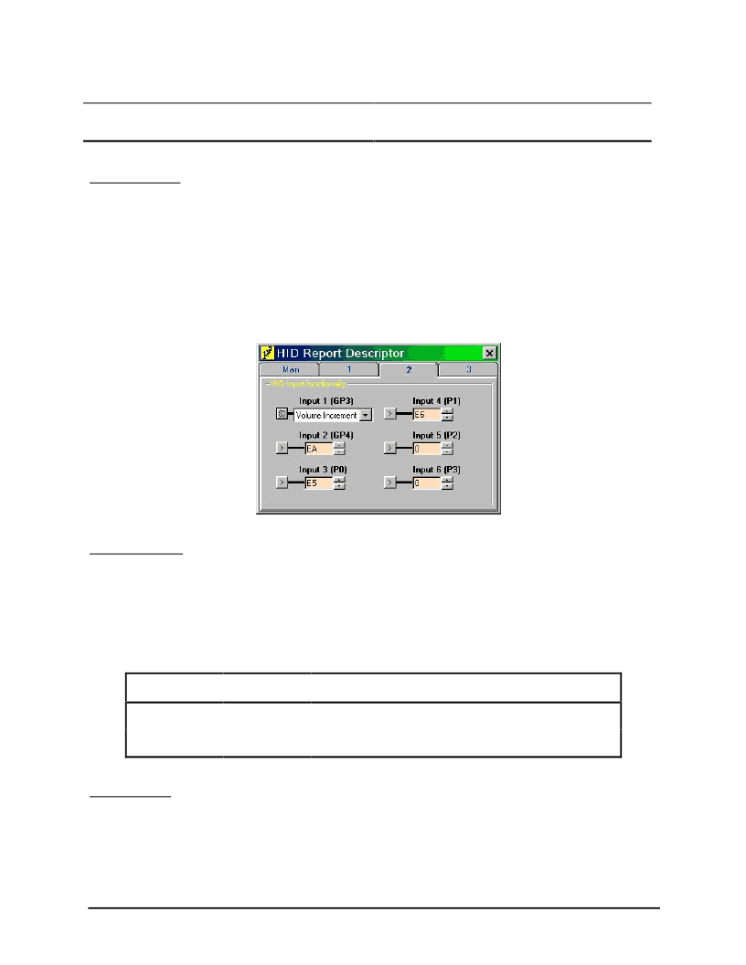
UniCoDes
enables you to set different functions with the command / button
Descriptors
. This will pop-up a new
window in which you must select the button
HID Report Descriptors
. Now you have three TAB fields to choose
from. Select the second tabfield titled as
HID input functionality
. Default, the values are set to Volume controls
for HID input 1 & 2. See figure below.
10
Fig. 2-4
HID functions definitions
* Selector outputs:
In case you are using topology 2, you have the ability to control the selector with GP2. This pin is defined at two
places:
-
Address 0Bh defines the logical level of GP2.
-
Address 13h defines the preferred Terminal to use.
The table below gives the possible combinations and results of each configuration:
Selector
Preferred state
output level
Terminal 1
Normal
PGA settings for Terminal 1 takes effect with GP2 = 0V
Terminal 1
Inverted
PGA settings for Terminal 1 takes effect with GP2 = Vdd
Terminal 2
Normal
PGA settings for Terminal 2 takes effect with GP2 = Vdd
Terminal 2
Inverted
PGA settings for Terminal 2 takes effect with GP2 = 0V
Table 2-2
Possible combinations for definition of GP2
Selector
Results
* Interrupt input:
The firmware uses two different methods for detecting changes on the expander inputs. The first one applies
serial polling in which the inputs are scanned every 20ms. This frequency is defined within the firmware and is
not settable. The other method is by implementing hardware interrupt. Everytime that the expander detects
changes at the input lines, it will produce an interrupt signal at the respective pin (13) of the expander. The
firmware will be triggered by this via the GP0 interrupt input and will update all respective registers.
相關(guān)PDF資料 |
PDF描述 |
|---|---|
| UDA1331H | Universal Serial Bus USB Audio Playback Peripheral APP |
| UDA1334BT | Low power audio DAC |
| UDA1334TS | Low power audio DAC |
| UDA1335H | Universal Serial Bus USB Audio Playback Recording Peripheral APRP |
| UDA1340 | Low-voltage low-power stereo audio CODEC with DSP features |
相關(guān)代理商/技術(shù)參數(shù) |
參數(shù)描述 |
|---|---|
| UDA1328 | 制造商:PHILIPS 制造商全稱:NXP Semiconductors 功能描述:Multi-channel filter DAC |
| UDA1328T | 制造商:PHILIPS 制造商全稱:NXP Semiconductors 功能描述:Multi-channel filter DAC |
| UDA1330A | 制造商:PHILIPS 制造商全稱:NXP Semiconductors 功能描述:Low-cost stereo filter DAC |
| UDA1330ATS | 制造商:PHILIPS 制造商全稱:NXP Semiconductors 功能描述:Low-cost stereo filter DAC |
| UDA1330ATS/N2 | 制造商:NXP Semiconductors 功能描述:IC DAC AUDIO STEREO 16-SSOP 制造商:NXP Semiconductors 功能描述:IC, DAC, AUDIO, STEREO, 16-SSOP |
發(fā)布緊急采購,3分鐘左右您將得到回復(fù)。