- 您現(xiàn)在的位置:買賣IC網(wǎng) > PDF目錄272835 > TXS100ZY-P2 (POWER-ONE INC) 1-OUTPUT 120 W DC-DC REG PWR SUPPLY MODULE PDF資料下載
參數(shù)資料
| 型號: | TXS100ZY-P2 |
| 廠商: | POWER-ONE INC |
| 元件分類: | 電源模塊 |
| 英文描述: | 1-OUTPUT 120 W DC-DC REG PWR SUPPLY MODULE |
| 封裝: | 2.400 X 3.450 INCH, 0.500 INCH HEIGHT, 3/4 BRICK PACKAGE-14 |
| 文件頁數(shù): | 16/27頁 |
| 文件大?。?/td> | 2635K |
| 代理商: | TXS100ZY-P2 |
第1頁第2頁第3頁第4頁第5頁第6頁第7頁第8頁第9頁第10頁第11頁第12頁第13頁第14頁第15頁當(dāng)前第16頁第17頁第18頁第19頁第20頁第21頁第22頁第23頁第24頁第25頁第26頁第27頁

Product Specification
TXS Series: 75…120 A DC-DC Converters
36 to 75 V DC Input, 1.2, 1.5, 1.8, 2.0 and 2.5 V Output, 90 W to 250 W
REV. FEB 18, 2003
23 of 27
www.power-one.com
Thermal Considerations
TXS converters achieve one of the highest current
and power densities on the market. This would be
useless, if in practise the available current should
be reduced a lot because of cooling problems.
But TXS converters achieve also the highest full
load efficiency on the market and use a unique
thermal design which makes them to real high
density, high current converters.
Maximum Base Plate Temperature
To ensure reliable long term operation, and to
comply with safety agency requirements, the base
plate temperature (TBP) should always be kept
below
100 °C.
The
maximum
base
plate
temperature is defined by two conditions:
Maximum multilayer temperature
≤ 120 °C.
(UL 130 °C print material is used: Power-One
designs use normally 10 K safety margin).
Maximum opto-coupler temperature
≤ 100 °C.
(Device limits, otherwise accelerated aging)
If the base plate temperature stays below 100 °C,
both of the above limits are kept under all
operating and cooling conditions.
The maximum base plate temperature is limited by
the temperature protection, but should be verified
after system integration. TBP can be measured on
the temperature measuring point on the base
plate. See mechanical drawing for location.
Thermal Resistance
To operate the converters below the maximum
base plate temperature, sufficient cooling should
be provided. The modules can be cooled by
conduction, convection and radiation to the
surrounding environment.
The path for the heat transport can be described
with a thermal resistance. A low thermal
resistance allows a lot of heat or loss to flow from a
hot component x to the surrounding y.
Rthxy = (Tx - Ty) / PLoss
[K/W]
The thermal resistance between x and y is defined
as temperature difference between the two parts,
divided through the amount of loss flowing from the
hot to the cool part (see report “Thermal
performace of TXS” on the TXS product CD ROM
for further information).
TXS provide two main ways for heat transport:
Heat can be transported to the motherboard and to
ambient.
Base Plate to Motherboard RthBP-PCB
TXS converters provide an efficient way to
transport heat to the motherboard over the pins
and the case. Since the efficiency of this method
varies from design to design, it can’t be predicted.
(See report: “TXS layout considerations”)
Base Plate to Ambient RthBP-A
TXS modules are designed for forced convection
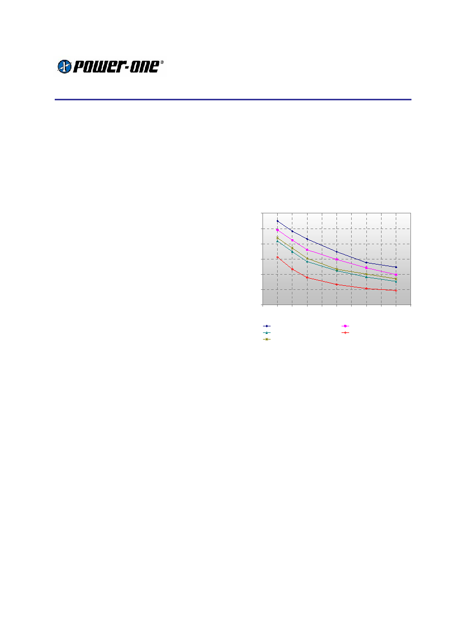
cooling. To estimate the thermal resistance at
different airflows the following graph can be used:
Thermal Resistance v's Air-Flow Rate
0.00
0.50
1.00
1.50
2.00
2.50
3.00
50
100
150
200
250
300
350
400
450
500
550
Air-Flow Rate (LFM)
Rth
(K/
W
)
Without Heat Sink
6.1mm (0.24'') Heat Sink
13mm (0.51'') Heat Sink (CUT)
24.1mm (0.95'') Heat Sink
11.4mm (0.45'') Heat Sink
Figure 53:
Thermal resistances at laminar airflow
TXS modules are designed to work without
additional heat sink. But it is possible to attach an
external heat sink to the base plate.
Heat sinks can efficiently help to increase the
thermal safety margin or to increase the available
power if the available airflow in a system is not
sufficient.
Calculation of the Required Airflow
The thermal resistance RthBP-A allows determining
the required airflow or heat sink, for a given
ambient temperature and operating condition.
1
The operating conditions define the loss of the
converter: Loss figures for different output
voltages, input voltage ranges, and output
currents can be found on page 8. They should
be corrected with the factors of Table 7 for the
targeted base plate temperature.
2
The required thermal resistance for a given
environment (TBP, TA) and loss can be
calculated using the formula from above:
RthBP-A = (TBP -TA) / PLoss. To remember: The
base plate temperature should not be
相關(guān)PDF資料 |
PDF描述 |
|---|---|
| TXS120ZA-N2V | 1-OUTPUT 180 W DC-DC REG PWR SUPPLY MODULE |
| TXS120ZA-R3H | 1-OUTPUT 180 W DC-DC REG PWR SUPPLY MODULE |
| TXS120ZY-P21V | 1-OUTPUT 144 W DC-DC REG PWR SUPPLY MODULE |
| TXS75ZY-P2R2V | 1-OUTPUT 90 W DC-DC REG PWR SUPPLY MODULE |
| TXS80ZD-3V | 1-OUTPUT 200 W DC-DC REG PWR SUPPLY MODULE |
相關(guān)代理商/技術(shù)參數(shù) |
參數(shù)描述 |
|---|---|
| TXS10AU08AI | 制造商:TE Connectivity 功能描述: |
| TXS10AU12AI | 功能描述:環(huán)形MIL規(guī)格應(yīng)變消除裝置與適配器 ADAPTER: RoHS:否 制造商:Amphenol Industrial 產(chǎn)品:Cable Clamps 類型:Bushing Cable Clamps MIL 類型:MIL-DTL-5015 系列:97 外殼大小:16S, 16 匹配樣式:Threaded 主體材料:Aluminum Alloy 主體類型:Straight |
| TXS10P-100A | 制造商:TOPSTEK 制造商全稱:TOPSTEK 功能描述:Anti-Magnet AC Current Sensors |
| TXS18X | 制造商:YSTONE 制造商全稱:Yellow Stone Corp 功能描述:TAPED LED LAMP |
| TXS2-1.5V | 功能描述:低信號繼電器 - PCB 2 Form C 2A 30VDC 1.5VDC RoHS:否 制造商:NEC 觸點形式:2 Form C (DPDT-BM) 觸點電流額定值: 線圈電壓:5 V 最大開關(guān)電流:1 A 線圈電流:1 A 線圈類型:Non-Latching 功耗:140 mW 端接類型:SMT 絕緣: 介入損耗: |
發(fā)布緊急采購,3分鐘左右您將得到回復(fù)。