- 您現(xiàn)在的位置:買賣IC網(wǎng) > PDF目錄373626 > TDA9112 (意法半導(dǎo)體) LOW-COST I2C CONTROLLED DEFLECTION PROCESSOR FOR MULTISYNC MONITOR PDF資料下載
參數(shù)資料
| 型號: | TDA9112 |
| 廠商: | 意法半導(dǎo)體 |
| 英文描述: | LOW-COST I2C CONTROLLED DEFLECTION PROCESSOR FOR MULTISYNC MONITOR |
| 中文描述: | 低費用的I2C可控?fù)隙榷嗤斤@示器處理器 |
| 文件頁數(shù): | 31/51頁 |
| 文件大小: | 621K |
| 代理商: | TDA9112 |
第1頁第2頁第3頁第4頁第5頁第6頁第7頁第8頁第9頁第10頁第11頁第12頁第13頁第14頁第15頁第16頁第17頁第18頁第19頁第20頁第21頁第22頁第23頁第24頁第25頁第26頁第27頁第28頁第29頁第30頁當(dāng)前第31頁第32頁第33頁第34頁第35頁第36頁第37頁第38頁第39頁第40頁第41頁第42頁第43頁第44頁第45頁第46頁第47頁第48頁第49頁第50頁第51頁
TDA9112
31/51
rabolas of 4th order for corner corrections inde-
pendently at the top and at the bottom) are gener-
ated from the output vertical deflection drive wave-
form, they all track with real vertical amplitude and
position (including breathing compensation), thus
being fixed on the screen. Refer to I
2
C BUS CON-
TROL REGISTERMAP for details on I
2
C bus con-
trols.
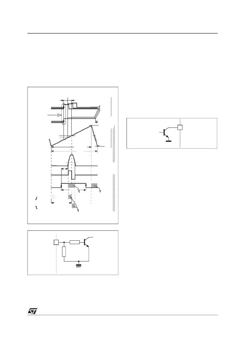
Figure 7. Horizontal timing diagram
Figure 8. HFly input configuration
9.3.6 - Output Section
The H-drive signal is inhibited (high level) during
flyback pulse, and also when
V
CC
is too low, when
X-ray protection is activated (XRayAlarm I
2
C bus
flag set to 1) and when I
2
C bus bit HBOutEn is set
to 0 (default position).
The duty cycle of the H-drive signal is controlled
via I
2
C bus register HDUTY This is overruled dur-
ing soft-start and soft-stop procedures (see sub
chapter Soft-start and soft-stop on H-drive on
page 31 and Figure 10).
The PLL2 is followed by a rapid phase shifting
which accepts the signal from H-moiré canceller
(see sub chapter Horizontal moiré cancellation on
page 31)
The output stage consists of a NPN bipolar tran-
sistor, the collector of which is routed to HOut pin
(see Figure 9).
Figure 9. HOut configuration
Non-conductive state of HOT (Horizontal Output
Transistor) must correspond to non-conductive
state of the device output transistor.
9.3.7 - Soft-start and soft-stop on H-drive
The soft-start and soft-stop procedure is carried
out at each switch-on or switch-off of the H-drive
signal, either via HBOutEn I
2
C bus bit or after re-
set of XRayAlarm I
2
C bus flag, to protect external
power components.By itssecond function, the ex-
ternal capacitor on pin HPosF is used to time out
this procedure, during which the duty cycle of H-
drive signalstarts at its maximum (“
t
Hoff
/T
H
for soft
start/stop” in electrical specifications) and slowly
decreases to the value determined by the control
I
2
C bus register HDUTY (vice versa at soft-stop).
This is controlled by voltage on pin HPosF. See
Figure 10 and sub chapter Safety functions on
page 39.
9.3.8 - Horizontal moiré cancellation
The horizontal moiré canceller is intended to blur a
potential beat between the horizontal video pixel
period and the CRT pixel width, which causes vis-
ible moiré patterns in the picture.
It introduces a microscopic indent on horizontal
scan lines by injecting little controlled phase shifts
to output circuitry of the horizontal section. Their
amplitude is adjustable through HMOIRE I
2
C bus
control.
The behaviour of horizontal moiré is to be opti-
mised for different deflection design configurations
using HMoiré I
2
C bus bit. This bit is to be kept at 0
H-flyback
PLL2
control
H-drive
(on HOut)
current
V
ThrHFly
+
-
t
S
t
Hoff
H-drive
region
H-drive
region
t
ph(max)
inhibited
t
S
: HOT storage time
H-Osc
(VCO)
V
S(0)
7/8T
H
T
H
V
HOThrHi
max.
med.
min.
V
HPosF
H-sync
(polarized)
REF1
(internal)
t
Hph
min
max
HPOS
(I
C)
max.
med.
min.
PLL1lock
V
HOThrLo
P
P
ON
forced high
forced low
OFF
ON
GND
~20k
HFly 12
~500
int.
ext.
26
int.
ext.
HOut
相關(guān)PDF資料 |
PDF描述 |
|---|---|
| TDA9113 | LOW-COST I2C CONTROLLED DEFLECTION PROCESSOR FOR MULTISYNC MONITOR |
| TDA9115 | LOW-COST I2C CONTROLLED DEFLECTION PROCESSOR FOR MULTISYNC MONITOR |
| TDA9116 | LOW-COST I2C CONTROLLED DEFLECTION PROCESSOR FOR MULTISYNC MONITOR |
| TDA9201 | WIDE BAND VIDEO PREAMPLIFIER |
| TDA9203 | I2C BUS CONTROLLED 70MHz RGB PREAMPLIFIER |
相關(guān)代理商/技術(shù)參數(shù) |
參數(shù)描述 |
|---|---|
| TDA9112A | 制造商:STMICROELECTRONICS 制造商全稱:STMicroelectronics 功能描述:HIGH-END I2C CONTROLLED DEFLECTION PROCESSOR FOR MULTISYNC MONITOR |
| TDA9113 | 制造商:STMICROELECTRONICS 制造商全稱:STMicroelectronics 功能描述:LOW-COST I2C CONTROLLED DEFLECTION PROCESSOR FOR MULTISYNC MONITOR |
| TDA9115 | 制造商:STMICROELECTRONICS 制造商全稱:STMicroelectronics 功能描述:LOW-COST I2C CONTROLLED DEFLECTION PROCESSOR FOR MULTISYNC MONITOR |
| TDA9116 | 制造商:STMICROELECTRONICS 制造商全稱:STMicroelectronics 功能描述:LOW-COST I2C CONTROLLED DEFLECTION PROCESSOR FOR MULTISYNC MONITOR |
| TDA9118 | 制造商:PHILIPS 制造商全稱:NXP Semiconductors 功能描述:行/場掃描處理電路 |
發(fā)布緊急采購,3分鐘左右您將得到回復(fù)。