- 您現(xiàn)在的位置:買賣IC網(wǎng) > PDF目錄98145 > ST72621J2B1 (STMICROELECTRONICS) 8-BIT, MROM, 8 MHz, MICROCONTROLLER, PDIP20 PDF資料下載
參數(shù)資料
| 型號(hào): | ST72621J2B1 |
| 廠商: | STMICROELECTRONICS |
| 元件分類: | 微控制器/微處理器 |
| 英文描述: | 8-BIT, MROM, 8 MHz, MICROCONTROLLER, PDIP20 |
| 封裝: | 0.300 INCH, PLASTIC, DIP-20 |
| 文件頁(yè)數(shù): | 108/136頁(yè) |
| 文件大?。?/td> | 2475K |
| 代理商: | ST72621J2B1 |
第1頁(yè)第2頁(yè)第3頁(yè)第4頁(yè)第5頁(yè)第6頁(yè)第7頁(yè)第8頁(yè)第9頁(yè)第10頁(yè)第11頁(yè)第12頁(yè)第13頁(yè)第14頁(yè)第15頁(yè)第16頁(yè)第17頁(yè)第18頁(yè)第19頁(yè)第20頁(yè)第21頁(yè)第22頁(yè)第23頁(yè)第24頁(yè)第25頁(yè)第26頁(yè)第27頁(yè)第28頁(yè)第29頁(yè)第30頁(yè)第31頁(yè)第32頁(yè)第33頁(yè)第34頁(yè)第35頁(yè)第36頁(yè)第37頁(yè)第38頁(yè)第39頁(yè)第40頁(yè)第41頁(yè)第42頁(yè)第43頁(yè)第44頁(yè)第45頁(yè)第46頁(yè)第47頁(yè)第48頁(yè)第49頁(yè)第50頁(yè)第51頁(yè)第52頁(yè)第53頁(yè)第54頁(yè)第55頁(yè)第56頁(yè)第57頁(yè)第58頁(yè)第59頁(yè)第60頁(yè)第61頁(yè)第62頁(yè)第63頁(yè)第64頁(yè)第65頁(yè)第66頁(yè)第67頁(yè)第68頁(yè)第69頁(yè)第70頁(yè)第71頁(yè)第72頁(yè)第73頁(yè)第74頁(yè)第75頁(yè)第76頁(yè)第77頁(yè)第78頁(yè)第79頁(yè)第80頁(yè)第81頁(yè)第82頁(yè)第83頁(yè)第84頁(yè)第85頁(yè)第86頁(yè)第87頁(yè)第88頁(yè)第89頁(yè)第90頁(yè)第91頁(yè)第92頁(yè)第93頁(yè)第94頁(yè)第95頁(yè)第96頁(yè)第97頁(yè)第98頁(yè)第99頁(yè)第100頁(yè)第101頁(yè)第102頁(yè)第103頁(yè)第104頁(yè)第105頁(yè)第106頁(yè)第107頁(yè)當(dāng)前第108頁(yè)第109頁(yè)第110頁(yè)第111頁(yè)第112頁(yè)第113頁(yè)第114頁(yè)第115頁(yè)第116頁(yè)第117頁(yè)第118頁(yè)第119頁(yè)第120頁(yè)第121頁(yè)第122頁(yè)第123頁(yè)第124頁(yè)第125頁(yè)第126頁(yè)第127頁(yè)第128頁(yè)第129頁(yè)第130頁(yè)第131頁(yè)第132頁(yè)第133頁(yè)第134頁(yè)第135頁(yè)第136頁(yè)

ST7262
73/136
SERIAL COMMUNICATIONS INTERFACE (Cont’d)
10.5.4.7 Parity Control
Parity control (generation of parity bit in transmis-
sion and parity checking in reception) can be ena-
bled by setting the PCE bit in the SCICR1 register.
Depending on the frame length defined by the M
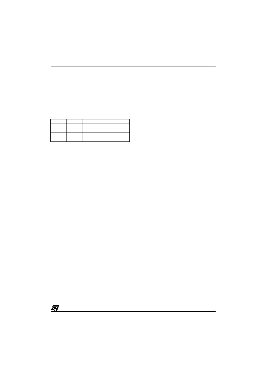
bit, the possible SCI frame formats are as listed in
Table 20. Frame Formats
Legend: SB = Start Bit, STB = Stop Bit,
PB = Parity Bit
Note: In case of wake up by an address mark, the
MSB bit of the data is taken into account and not
the parity bit
Even parity: the parity bit is calculated to obtain
an even number of “1s” inside the frame made of
the 7 or 8 LSB bits (depending on whether M is
equal to 0 or 1) and the parity bit.
Ex: data=00110101; 4 bits set => parity bit will be
0 if even parity is selected (PS bit = 0).
Odd parity: the parity bit is calculated to obtain an
odd number of “1s” inside the frame made of the 7
or 8 LSB bits (depending on whether M is equal to
0 or 1) and the parity bit.
Ex: data=00110101; 4 bits set => parity bit will be
1 if odd parity is selected (PS bit = 1).
Transmission mode: If the PCE bit is set then the
MSB bit of the data written in the data register is
not transmitted but is changed by the parity bit.
Reception mode: If the PCE bit is set then the in-
terface checks if the received data byte has an
even number of “1s” if even parity is selected
(PS=0) or an odd number of “1s” if odd parity is se-
lected (PS=1). If the parity check fails, the PE flag
is set in the SCISR register and an interrupt is gen-
erated if PIE is set in the SCICR1 register.
10.5.4.8 SCI Clock Tolerance
During reception, each bit is sampled 16 times.
The majority of the 8th, 9th and 10th samples is
considered as the bit value. For a valid bit detec-
tion, all the three samples should have the same
value otherwise the noise flag (NF) is set. For ex-
ample: if the 8th, 9th and 10th samples are 0, 1
and 1 respectively, then the bit value will be “1”,
but the Noise Flag bit is be set because the three
samples values are not the same.
Consequently, the bit length must be long enough
so that the 8th, 9th and 10th samples have the de-
sired bit value. This means the clock frequency
should not vary more than 6/16 (37.5%) within one
bit. The sampling clock is resynchronized at each
start bit, so that when receiving 10 bits (one start
bit, 1 data byte, 1 stop bit), the clock deviation
must not exceed 3.75%.
Note: The internal sampling clock of the microcon-
troller samples the pin value on every falling edge.
Therefore, the internal sampling clock and the time
the application expects the sampling to take place
may be out of sync. For example: If the baud rate
is 15.625 kbaud (bit length is 64s), then the 8th,
9th and 10th samples will be at 28s, 32s & 36s
respectively (the first sample starting ideally at
0s). But if the falling edge of the internal clock oc-
curs just before the pin value changes, the sam-
ples would then be out of sync by ~4us. This
means the entire bit length must be at least 40s
(36s for the 10th sample + 4s for synchroniza-
tion with the internal sampling clock).
M bit
PCE bit
SCI frame
0
| SB | 8 bit data | STB |
0
1
| SB | 7-bit data | PB | STB |
1
0
| SB | 9-bit data | STB |
1
| SB | 8-bit data PB | STB |
相關(guān)PDF資料 |
PDF描述 |
|---|---|
| ST72621J2T1 | 8-BIT, MROM, 8 MHz, MICROCONTROLLER, PDSO20 |
| ST72P621L4M1 | 8-BIT, MROM, 8 MHz, MICROCONTROLLER, PDSO34 |
| ST72623F2M1L | 8-BIT, MROM, 4 MHz, MICROCONTROLLER, PDSO34 |
| ST7263BK1B/XXX | 8-BIT, MROM, 8 MHz, MICROCONTROLLER, PDIP32 |
| ST72652AR4T1/XXX | 8-BIT, MROM, MICROCONTROLLER, PQFP64 |
相關(guān)代理商/技術(shù)參數(shù) |
參數(shù)描述 |
|---|---|
| ST7263-EMU2 | 功能描述:仿真器/模擬器 ST7 Emulator Board RoHS:否 制造商:Blackhawk 產(chǎn)品:System Trace Emulators 工具用于評(píng)估:C6000, C5000, C2000, OMAP, DAVINCI, SITARA, TMS470, TMS570, ARM 7/9, ARM Cortex A8/R4/M3 用于:XDS560v2 |
| ST7265X-EVAL/MS | 制造商:STMicroelectronics 功能描述:ST6 EVAL BD - Bulk |
| ST7265X-EVAL/PFD | 制造商:STMicroelectronics 功能描述:USB FLASH EVAL - Bulk |
| ST7266 | 制造商:6940 功能描述:ST7266 |
| ST7267C8T1L | 制造商:STMicroelectronics 功能描述: |
發(fā)布緊急采購(gòu),3分鐘左右您將得到回復(fù)。