- 您現(xiàn)在的位置:買賣IC網(wǎng) > PDF目錄373368 > SC88E43 (Electronic Theatre Controls, Inc.) EXTENDED VOLTAGE CALLING NUMBER IDENTIFICATION CIRCUIT 2 PDF資料下載
參數(shù)資料
| 型號: | SC88E43 |
| 廠商: | Electronic Theatre Controls, Inc. |
| 英文描述: | EXTENDED VOLTAGE CALLING NUMBER IDENTIFICATION CIRCUIT 2 |
| 中文描述: | 更廣的電壓主叫號碼識別電路2 |
| 文件頁數(shù): | 8/25頁 |
| 文件大小: | 389K |
| 代理商: | SC88E43 |
Silan
Semiconductors
SC88E43
HANGZHOU SILAN MICROELECTRONICS JOINT-STOCK CO.,LTD
Rev: 1.0
2000.12.31
8
(continued)
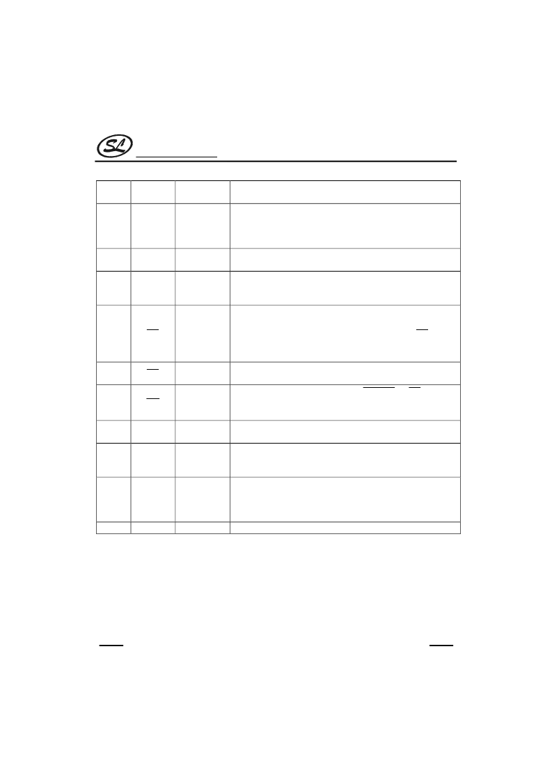
Pin
No.
Symbol
I/O
Function
15
FSKen
CMOS Input
FSK Enable. Must be high for FSK demodulation. This pin should be
set low to prevent the FSK demodulator from reacting to extraneous
signals (such as speech, alert signal and DTMF which are all in the
same frequency band as FSK).
3-wire Interface: Data Clock. In mode 0 (MODE pin low), this pin is an
output. In mode 1 (MODE pin high), this pin is an input.
3-wire Interface: Data. In mode 0 the FSK data appears at the pin
once demodulated. In mode 1 the FSK data is shifted out on the rising
edge of the microcontroller supplied DCLK.
3-wire Interface: Data Ready. Active low. In mode 0 this output goes
low after the last DCLK pulse of each data word. This identifies the 8-
bit word boundary on the serial output stream. Typically,
DR
is used
to latch 8-bit words from a serial-to-parallel converter into a
microcontroller. In mode 1 this pin will signal the availability of data.
Carrier Detect. Active low. A logic low indicates the presence of in-
band signal at the output of the FSK bandpass filter.
Interrupt. Active low. It is active when
TRIGout
or
DR
is low, or
16
DCLK
CMOS
Input/Output
17
DATA
CMOS Output
18
DR
CMOS Output
19
CD
CMOS Output
20
INT
Open Drain
Output
StD is high. This output stays low until all three signals have become
inactive.
Dual Tone Alert Signal Delayed Steering Output. When high, it
indicates that a guard time qualified alert signal has been detected.
Dual Tone Alert Signal Early Steering Output. Alert signal detection
output. Used in conjunction with St/GT and external circuitry to
implement the detect and non-detect guard times.
Dual Tone Alert Signal Steering Input/Guard Time. A voltage greater
than V
TGt
(see figure 4) at the St/GT pin causes the device to indicate
that a dual tone has been detected by asserting StD high. A voltage
less than V
TGt
frees the device to accept a new dual tone.
Positive Power Supply.
21
StD
CMOS Output
22
ESt
CMOS Output
23
St/GT
Analog Input /
CMOS Output
24
V
DD
--
相關(guān)PDF資料 |
PDF描述 |
|---|---|
| SC88E43S | EXTENDED VOLTAGE CALLING NUMBER IDENTIFICATION CIRCUIT 2 |
| SC9016-000 | FET Chip Mounting Capacitors (MIS) |
| SC9017-000 | FET Chip Mounting Capacitors (MIS) |
| SC9106 | TONE RINGER SC9106 |
| SC9148B | FOR INFRARED REMOTE CONTROL TRANSMITTER |
相關(guān)代理商/技術(shù)參數(shù) |
參數(shù)描述 |
|---|---|
| SC88E43S | 制造商:未知廠家 制造商全稱:未知廠家 功能描述:EXTENDED VOLTAGE CALLING NUMBER IDENTIFICATION CIRCUIT 2 |
| SC-89 | 制造商:VISHAY 制造商全稱:Vishay Siliconix 功能描述:P-Channel 1.8-V (G-S) MOSFET |
| SC-8986 | 制造商:SCBT 制造商全稱:SCBT 功能描述:HNF-1 (H-205) |
| SC8B-1.8M/BK-R | 制造商:Tai Yip Electrical 功能描述: |
| SC8B-10M/BK-R | 制造商:Tai Yip Electrical 功能描述: |
發(fā)布緊急采購,3分鐘左右您將得到回復(fù)。