- 您現(xiàn)在的位置:買賣IC網(wǎng) > PDF目錄368145 > PSD303L Field Programmable Microcontroller Peripherals(可編程邏輯,16K位SRAM,19個(gè)可編程I/O,通用PLD有16個(gè)輸入) PDF資料下載
第1頁(yè)第2頁(yè)第3頁(yè)第4頁(yè)第5頁(yè)當(dāng)前第6頁(yè)第7頁(yè)第8頁(yè)第9頁(yè)第10頁(yè)第11頁(yè)第12頁(yè)第13頁(yè)第14頁(yè)

PSD3XX
Architecture
(Cont.)
PSD3XX – Application Note 022
1-206
Various EPROM sizes are offered in the PSD3XX series. The PSD3X1 contains 256K bits
of EPROM, the PSD3X2 contains 512K bits and the PSD3X3 provides 1 megabits. The
PSD3X2 and PSD3X3 devices contain a 4-bit page register to enable additional memory
map flexibility. This page register enables memory expansion by a factor of 16. For
example, 8-bit microcontrollers like the 80C31 that address only 64K of memory space can
now access over 1 meg bytes with either the PSD3X2 or PSD3X3.
Figure 3 illustrates the block configuration of the EPROM. It can be selected as separate
blocks that can be scattered throughout the memory space or concatenated into a single
block. This feature provides the designer with a great deal of flexibility and efficiency by
placing EPROM segments throughout the memory where they are most needed. The
SRAM block can also be programmed to appear in any part of the memory map. Some
possible examples are shown in Tables 1 and 2. The Table 1 memory map shows the
EPROM blocks concatenated together and starting at address 0 as they might look in a
simple 80C31 system. Table 2 illustrates the EPROM blocks separated and spread
throughout the memory map with the SRAM segment and the memory mapped I/O
between EPROM blocks.
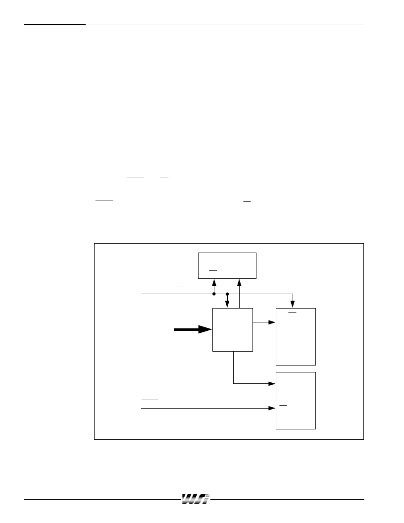
Internally the PSD3XX resolves the issue of Combined vs. Separate address spaces by
ORing the PSEN and RD signals when Combined space is specified. The EPROM and
SRAM segments will both be enabled if either of these signals is present. The address
decoder (PAD) will determine which of these is actually active. In the Separate mode, the
PSEN will enable only the EPROM output and the RD will enable only the SRAM and I/O
ports. Figures 4 and 5 illustrate how this is done.
INTERNAL
OE
OE
OE
CS
CS
CS
RD
ADDRESS
PSEN
I/O PORTS
PAD
SRAM
EPROM
Figure 4. Separate Code and Data Address Spaces
相關(guān)PDF資料 |
PDF描述 |
|---|---|
| PSD303 | Field Programmable Microcontroller Peripherals(可編程邏輯,16K位SRAM,19個(gè)可編程I/O,通用PLD有16個(gè)輸入) |
| PSD311L | Field Programmable Microcontroller Peripherals(可編程邏輯,16K位SRAM,19個(gè)可編程I/O,通用PLD有12個(gè)輸入) |
| PSD311 | Field Programmable Microcontroller Peripherals(可編程邏輯,16K位SRAM,19個(gè)可編程I/O,通用PLD有12個(gè)輸入) |
| PSD312-15IB | Field-Programmable Peripheral |
| PSD312-20IB | Field-Programmable Peripheral |
相關(guān)代理商/技術(shù)參數(shù) |
參數(shù)描述 |
|---|---|
| PSD303L-15J | 制造商:未知廠家 制造商全稱:未知廠家 功能描述:Field-Programmable Peripheral |
| PSD303L-15JI | 制造商:未知廠家 制造商全稱:未知廠家 功能描述:Field-Programmable Peripheral |
| PSD303L-15LI | 制造商:未知廠家 制造商全稱:未知廠家 功能描述:Field-Programmable Peripheral |
| PSD303L-15LM | 制造商:未知廠家 制造商全稱:未知廠家 功能描述:Field-Programmable Peripheral |
| PSD303L-15U | 制造商:未知廠家 制造商全稱:未知廠家 功能描述:Field-Programmable Peripheral |
發(fā)布緊急采購(gòu),3分鐘左右您將得到回復(fù)。