- 您現(xiàn)在的位置:買賣IC網(wǎng) > PDF目錄368095 > PPC405EP-3LB266CZ (APPLIEDMICRO INC) PowerPC 405EP Embedded Processor PDF資料下載
參數(shù)資料
| 型號: | PPC405EP-3LB266CZ |
| 廠商: | APPLIEDMICRO INC |
| 元件分類: | 微控制器/微處理器 |
| 英文描述: | PowerPC 405EP Embedded Processor |
| 中文描述: | 32-BIT, 266.66 MHz, RISC PROCESSOR, PBGA385 |
| 封裝: | 31 X 31 MM, LEAD FREE, PLASTIC, EBGA-385 |
| 文件頁數(shù): | 48/50頁 |
| 文件大?。?/td> | 373K |
| 代理商: | PPC405EP-3LB266CZ |
第1頁第2頁第3頁第4頁第5頁第6頁第7頁第8頁第9頁第10頁第11頁第12頁第13頁第14頁第15頁第16頁第17頁第18頁第19頁第20頁第21頁第22頁第23頁第24頁第25頁第26頁第27頁第28頁第29頁第30頁第31頁第32頁第33頁第34頁第35頁第36頁第37頁第38頁第39頁第40頁第41頁第42頁第43頁第44頁第45頁第46頁第47頁當前第48頁第49頁第50頁
PPC405EP – PowerPC 405EP Embedded Processor
48
AMCC
Revision 1.07 – September 10, 2007
Data Sheet
Initialization
The following describes the method by which initial chip settings are established when a system reset occurs.
Strapping
When the SysReset input is driven low (system reset), the state of certain I/O pins is read to enable default initial
conditions prior to PPC405EP start-up. The actual capture instant is the nearest system clock edge before the
deassertion of reset. These pins must be strapped using external pull-up (logical 1) or pull-down (logical 0)
resistors to select the desired default conditions. The recommended pull-up is 3k
Ω
to +3.3V or 10k
Ω
to +5V. The
recommended pull-down is 1K
Ω
to GND. These pins are use for strap functions only during reset. They are used
for other signals during normal operation. The following table lists the strapping pins along with their functions and
strapping options. The signal names assigned to the pins for normal operation appear below the pin number.
EEPROM
During reset, configuration values other than the internal default values can be read from a serial EEPROM
connected to the IIC port. The association of bits in the EEPROM with the configuration values and their default
values are covered in detail in the
PowerPC 405EP Embedded Processor User’s Manual
.
Note:
If P04 is strapped to 1, and the EEPROM is not connected or is defective, the PPC405EP remains in the
reset state and will not boot.
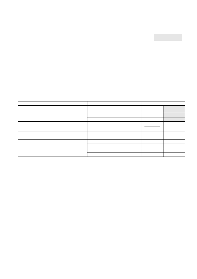
Table 16. Strapping Pin Assignments
Function
Option
Ball Strapping
P04
UART0_Tx
0
1
IIC EEPROM controller
If the controller is enabled, 32 bytes of configuration data
are read from the EEPROM.
Disable
Enable
EEPROM address (P04 = 1)
or
Boot ROM width (P04 = 0)
When P04 = 1, these pins set the high-order two
bits of the EEPROM base address.
When P04 = 0, these pins indicated the width of
the boot ROM.
N02
UART0_RTS
Y17
SysErr
High order EEPROM base address bits
Address bit
Address bit
8 bits
16 bits
reserved
reserved
0
0
1
1
0
1
0
1
相關PDF資料 |
PDF描述 |
|---|---|
| PPC405EP-3LB333C | PowerPC 405EP Embedded Processor |
| PPC405EP-3LB333CZ | PowerPC 405EP Embedded Processor |
| PPC405EX-NpAfffTx | PowerPC 405EX Embedded Processor |
| PPC405EX-SpAfffTx | PowerPC 405EX Embedded Processor |
| PPC405EZ-CSAfffTx | PowerPC 405EZ Embedded Processor |
相關代理商/技術參數(shù) |
參數(shù)描述 |
|---|---|
| PPC405EP-3LB333C | 制造商:AMCC 功能描述:MPU 405EP RISC 32BIT 0.18UM 333MHZ 3.3V 385BGA - Trays 制造商:AMCC 功能描述:AMCPPC405EP-3LB333C 32 BIT POWER PCCORE |
| PPC405EP-3LB333CZ | 制造商:AMCC 制造商全稱:Applied Micro Circuits Corporation 功能描述:PowerPC 405EP Embedded Processor |
| PPC405EX-CPA533T | 制造商:AMCC 功能描述: 制造商:AppliedMicro 功能描述: |
| PPC405EX-NPA333T | 制造商:AMCC 功能描述:32 BIT POWERPC CORE, UP TO 533 MHZ, 2 PCIE, 2 10/100/1G ETHE - Trays |
| PPC405EX-NPA400T | 制造商:AMCC 功能描述:32 BIT POWERPC CORE, UP TO 533 MHZ, 2 PCIE, 2 10/100/1G ETHE - Trays |
發(fā)布緊急采購,3分鐘左右您將得到回復。