- 您現(xiàn)在的位置:買賣IC網(wǎng) > PDF目錄369960 > PDI1394P11 (NXP SEMICONDUCTORS) 3-port physical layer interface PDF資料下載
參數(shù)資料
| 型號: | PDI1394P11 |
| 廠商: | NXP SEMICONDUCTORS |
| 元件分類: | 網(wǎng)絡接口 |
| 英文描述: | 3-port physical layer interface |
| 中文描述: | DATACOM, INTERFACE CIRCUIT, PQFP64 |
| 封裝: | 10 X 10 MM, 1.40 MM HEIGHT, PLASTIC, SOT-314-2, LQFP-64 |
| 文件頁數(shù): | 11/42頁 |
| 文件大小: | 233K |
| 代理商: | PDI1394P11 |
第1頁第2頁第3頁第4頁第5頁第6頁第7頁第8頁第9頁第10頁當前第11頁第12頁第13頁第14頁第15頁第16頁第17頁第18頁第19頁第20頁第21頁第22頁第23頁第24頁第25頁第26頁第27頁第28頁第29頁第30頁第31頁第32頁第33頁第34頁第35頁第36頁第37頁第38頁第39頁第40頁第41頁第42頁

Philips Semiconductors
Preliminary data
PDI1394P23
2-port/1-port 400 Mbps physical layer interface
2001 Sep 06
11
9.0
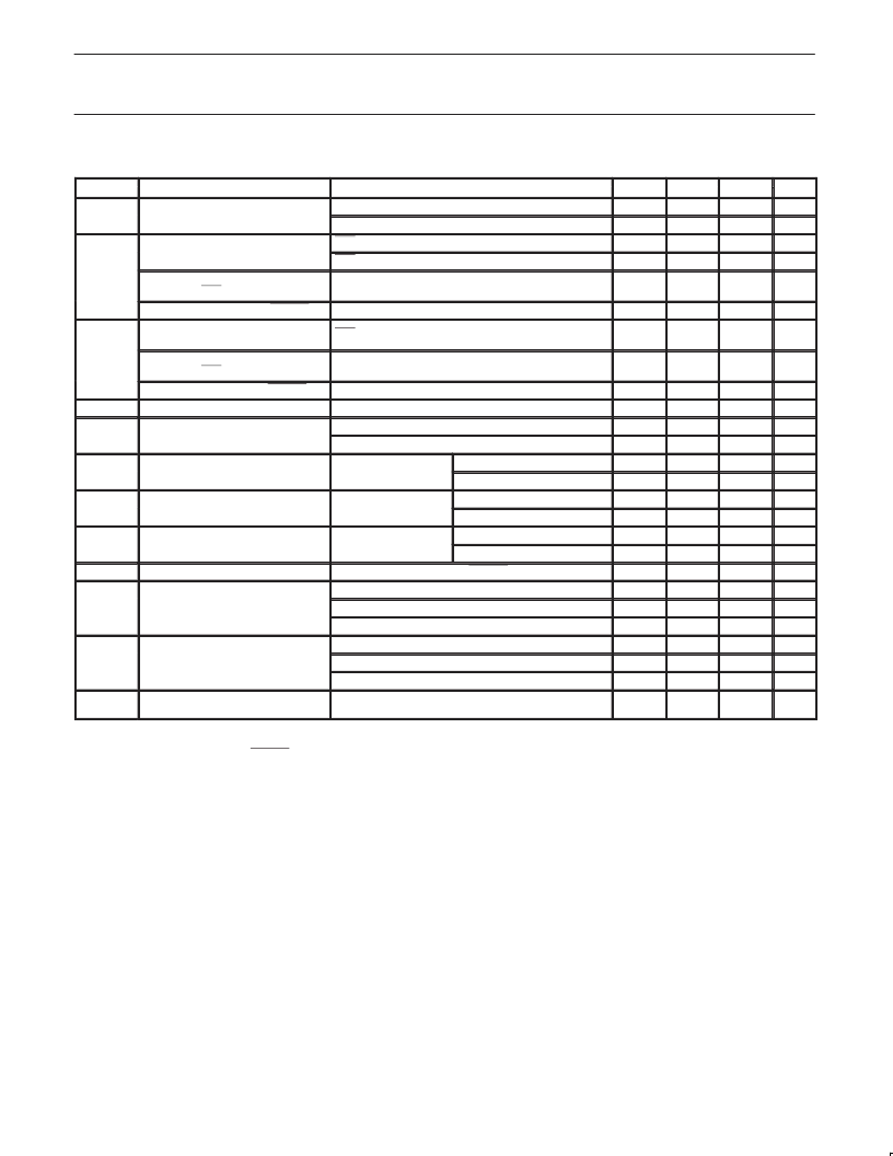
SYMBOL
RECOMMENDED OPERATING CONDITIONS
PARAMETER
CONDITION
MIN
3.0
2.7
1
2.3
2.6
TYP
3.3
3.0
—
—
MAX
3.6
3.6
—
—
UNIT
V
V
V
V
V
DD
Supply voltage
Source power node
Non-source power node
ISO = V
DD
, V
DD
>= 2.7 V
ISO = V
DD
, V
DD
>= 3.0 V
High-level input voltag
CTL0, CTL1, D0-D7
V
IH
High-level input voltage, C/LKON
2
,
PC0–PC2, ISO, PD
High-level input voltage, RESET
Low-level input voltage, LREQ,
CTL0, CTL1, D0–D7
Low-level input voltage, C/LKON
2
,
PC0–PC2, ISO, PD,
Low-level input voltage, RESET
Output current
0.7 V
DD
—
—
V
0.6 V
DD
—
—
—
ISO = V
DD
—
—
0.7
V
V
IL
—
—
0.2 V
DD
V
—
–6
118
168
1.165
1.165
0.935
0.935
0.523
0.523
2
—
—
—
—
—
—
—
0.3 V
DD
2.5
260
265
2.515
2.015
1
2.515
2.015
1
2.515
2.015
1
—
1.08
0.5
0.315
0.8
0.55
0.5
—
mA
mV
mV
V
V
V
V
V
V
ms
ns
ns
ns
ns
ns
ns
I
O
TPBIAS outputs
TPA, TPB cable inputs, during data reception
TPA, TPB cable inputs, during data arbitration
V
ID
Differential input voltage amplitude
Differential in ut voltage am litude
—
—
—
—
—
—
—
—
—
—
—
—
—
—
—
IC 100
V
IC-100
TPB common-mode input voltage
TPB common-mode in ut voltage
Speed signaling off
or S100 speed signal
Source power node
Non-source power node
Source power node
Non-source power node
Source power node
Non-source power node
IC 200
V
IC-200
TPB common-mode input voltage
TPB common-mode in ut voltage
S200 speed signal
S200 s eed signal
IC 400
V
IC-400
TPB common-mode input voltage
TPB common-mode in ut voltage
S400 speed signal
S400 s eed signal
t
PU
Power-up reset time
Set by capacitor between RESET pin and GND
TPA, TPB cable inputs, S100 operation
TPA, TPB cable inputs, S200 operation
TPA, TPB cable inputs, S400 operation
Between TPA and TPB cable inputs, S100 operation
Between TPA and TPB cable inputs, S200 operation
Between TPA and TPB cable inputs, S400 operation
Crystal connected according to Figure 10 or external
clock input at pin XI
Receive input jitter
Receive input skew
f
XTAL
Crystal or external clock frequency
24.5735
24.576
24.5785
MHz
NOTES:
1. For a node that does not source power to the bus (see Section 4.2.2.2 in the IEEE 1394-1995 standard).
2. C/LKON is only an input when RESET = 0.
相關PDF資料 |
PDF描述 |
|---|---|
| PDI1394P11BD | 3-port physical layer interface |
| PDI1394P25 | 1-port 400 Mbps physical layer interface |
| PDI1394P25BD | 1-port 400 Mbps physical layer interface |
| PDI1394P25EC | 1-port 400 Mbps physical layer interface |
| PDI1394P23BD | 2-port/1-port 400 Mbps physical layer interface |
相關代理商/技術(shù)參數(shù) |
參數(shù)描述 |
|---|---|
| PDI1394P11A | 制造商:PHILIPS 制造商全稱:NXP Semiconductors 功能描述:3-port physical layer interface |
| PDI1394P11ABD | 制造商:PHILIPS 制造商全稱:NXP Semiconductors 功能描述:3-port physical layer interface |
| PDI1394P11ABD-S | 制造商:未知廠家 制造商全稱:未知廠家 功能描述:Transceiver |
| PDI1394P11BD | 制造商:PHILIPS 制造商全稱:NXP Semiconductors 功能描述:3-port physical layer interface |
| PDI1394P11BD-S | 制造商:未知廠家 制造商全稱:未知廠家 功能描述:Transceiver |
發(fā)布緊急采購,3分鐘左右您將得到回復。