- 您現(xiàn)在的位置:買賣IC網(wǎng) > PDF目錄369944 > P83C524EFP (NXP SEMICONDUCTORS) CONN HEADER 12POS SGL PCB 30GOLD PDF資料下載
參數(shù)資料
| 型號(hào): | P83C524EFP |
| 廠商: | NXP SEMICONDUCTORS |
| 元件分類: | 微控制器/微處理器 |
| 英文描述: | CONN HEADER 12POS SGL PCB 30GOLD |
| 中文描述: | 8-BIT, MROM, 16 MHz, MICROCONTROLLER, PDIP40 |
| 封裝: | 0.600 INCH, PLASTIC, DIP-40 |
| 文件頁數(shù): | 43/76頁 |
| 文件大小: | 400K |
| 代理商: | P83C524EFP |
第1頁第2頁第3頁第4頁第5頁第6頁第7頁第8頁第9頁第10頁第11頁第12頁第13頁第14頁第15頁第16頁第17頁第18頁第19頁第20頁第21頁第22頁第23頁第24頁第25頁第26頁第27頁第28頁第29頁第30頁第31頁第32頁第33頁第34頁第35頁第36頁第37頁第38頁第39頁第40頁第41頁第42頁當(dāng)前第43頁第44頁第45頁第46頁第47頁第48頁第49頁第50頁第51頁第52頁第53頁第54頁第55頁第56頁第57頁第58頁第59頁第60頁第61頁第62頁第63頁第64頁第65頁第66頁第67頁第68頁第69頁第70頁第71頁第72頁第73頁第74頁第75頁第76頁

1997 Dec 15
43
Philips Semiconductors
Product specification
8-bit microcontrollers
P83C524; P80C528; P83C528
15.4
Wake-up from Power-down Mode
The Power-down mode of the P83C528 can also be
terminated by any one of the two external interrupts, IE0 or
IE1. A termination with an external interrupt does not affect
the internal data memory and does not affect the Special
Function Registers (SFRs). This gives the possibility to
exit Power-down without changing the port output levels.
To terminate the Power-down mode with an external
interrupt, IE0 or IE1 must be switched to be level-sensitive
and must be enabled. The external interrupt input signal
INT0 and INT1 must be kept LOW till the oscillator has
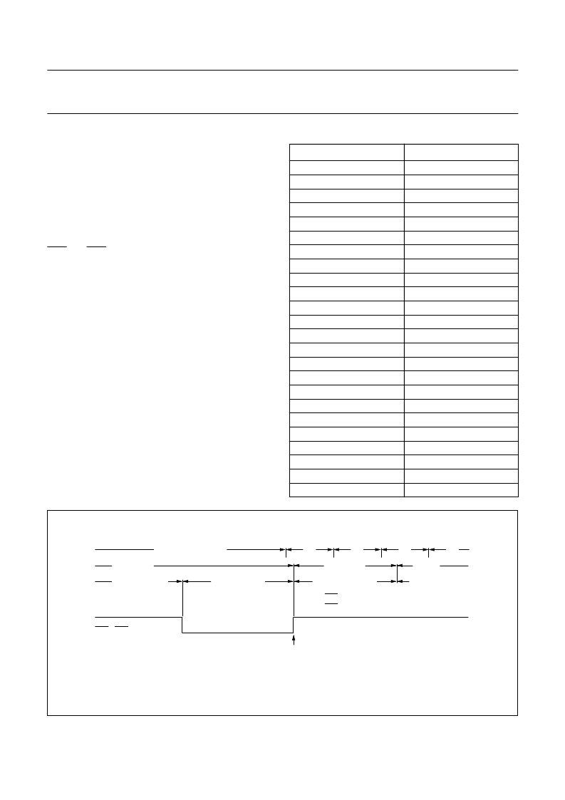
restarted and stabilized (see Fig.21).
In order to prevent any interrupt priority problems during
wake-up, the priority of the desired wake-up interrupt
should be higher than the priorities of all other enabled
interrupt sources. The instruction following the one that put
the device into the Power-down mode will be the first one
which will be executed after an interrupt has been
serviced.
Table 29
Internal registers status after a RESET
REGISTER
CONTENTS
ACC
B
DPH, DPL
IE
IP
PCH, PCL
PCON
PSW
P0 to P3
SBUF
SCON
SP
TCON
TMOD
TH0, TL0
TH1, TL1
T2CON
TH2, TL2
RCAP2H, RCAP2L
S1BIT
S1INT
S1SCS
T3
WDCON
00H
00H
00H
0000 0000B
X000 0000B
00H
0XXX 0000B
00H
FFH
Indeterminate
00H
07H
00H
00H
00H
00H
00H
00H
00H
X000 0000B
0XXX XXXXB
XXX0 0000B
00H
A5H
Fig.21 Wake up by external interrupt input.
MBC508 - 1
oscillator stopped
oscillator start up
min. 20 ms
power down
internal timing stopped
C1
C1
C1
C2
IDLE MODE
LCALL
interrupt routine
set external
interrupt latch
INT0 / INT1
INT1 1 cycle
INT0 2 cycles
interrupts are polled
相關(guān)PDF資料 |
PDF描述 |
|---|---|
| P83C524IBA | 8-bit microcontrollers |
| P83C524IBB | 8-bit microcontrollers |
| P83C524IFB | 8-bit microcontrollers |
| P83C524IFP | 8-bit microcontrollers |
| P83C524IBP | 8-bit microcontrollers |
相關(guān)代理商/技術(shù)參數(shù) |
參數(shù)描述 |
|---|---|
| P83C524FFA | 制造商:未知廠家 制造商全稱:未知廠家 功能描述:8-Bit Microcontroller |
| P83C524FFP | 制造商:未知廠家 制造商全稱:未知廠家 功能描述:8-Bit Microcontroller |
| P83C524FHA | 制造商:未知廠家 制造商全稱:未知廠家 功能描述:8-Bit Microcontroller |
| P83C524FHP | 制造商:未知廠家 制造商全稱:未知廠家 功能描述:8-Bit Microcontroller |
| P83C524GFA | 制造商:未知廠家 制造商全稱:未知廠家 功能描述:8-Bit Microcontroller |
發(fā)布緊急采購,3分鐘左右您將得到回復(fù)。