- 您現(xiàn)在的位置:買(mǎi)賣(mài)IC網(wǎng) > PDF目錄367697 > P51XAG33KBA (NXP SEMICONDUCTORS) XA 16-bit microcontroller family 32K/512 OTP/ROM/ROMless, watchdog, 2 UARTs PDF資料下載
參數(shù)資料
| 型號(hào): | P51XAG33KBA |
| 廠商: | NXP SEMICONDUCTORS |
| 元件分類(lèi): | 微控制器/微處理器 |
| 英文描述: | XA 16-bit microcontroller family 32K/512 OTP/ROM/ROMless, watchdog, 2 UARTs |
| 中文描述: | 16-BIT, MROM, 30 MHz, MICROCONTROLLER, PQCC44 |
| 封裝: | PLASTIC, LCC-44 |
| 文件頁(yè)數(shù): | 17/36頁(yè) |
| 文件大?。?/td> | 208K |
| 代理商: | P51XAG33KBA |
第1頁(yè)第2頁(yè)第3頁(yè)第4頁(yè)第5頁(yè)第6頁(yè)第7頁(yè)第8頁(yè)第9頁(yè)第10頁(yè)第11頁(yè)第12頁(yè)第13頁(yè)第14頁(yè)第15頁(yè)第16頁(yè)當(dāng)前第17頁(yè)第18頁(yè)第19頁(yè)第20頁(yè)第21頁(yè)第22頁(yè)第23頁(yè)第24頁(yè)第25頁(yè)第26頁(yè)第27頁(yè)第28頁(yè)第29頁(yè)第30頁(yè)第31頁(yè)第32頁(yè)第33頁(yè)第34頁(yè)第35頁(yè)第36頁(yè)

Philips Semiconductors
Product specification
XA-G3
XA 16-bit microcontroller family
32K/512 OTP/ROM/ROMless, watchdog, 2 UARTs
1999 Apr 07
17
CLOCKING SCHEME/BAUD RATE GENERATION
The XA UARTS clock rates are determined by either a fixed division
(modes 0 and 2) of the oscillator clock or by the Timer 1 or Timer 2
overflow rate (modes 1 and 3).
The clock for the UARTs in XA runs at 16x the Baud rate. If the
timers are used as the source for Baud Clock, since maximum
speed of timers/Baud Clock is Osc/4, the maximum baud rate is
timer overflow divided by 16 i.e. Osc/64.
In Mode 0, it is fixed at Osc/16. In Mode 2, however, the fixed rate is
Osc/32.
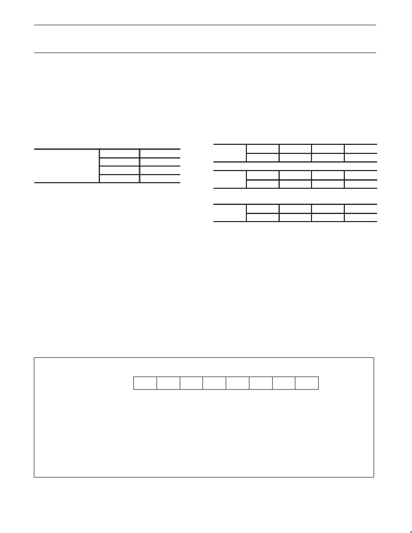
00
01
10
11
Osc/4
Osc/16
Osc/64
reserved
Pre-scaler
for all Timers T0 1 2
for all Timers T0,1,2
controlled by PT1, PT0
bits in SCR
Baud Rate for UART Mode 0:
Baud_Rate = Osc/16
Baud Rate calculation for UART Mode 1 and 3:
Baud_Rate = Timer_Rate/16
Timer_Rate = Osc/(N*(Timer_Range– Timer_Reload_Value))
where N = the TCLK prescaler value: 4, 16, or 64.
and Timer_Range =
256 for timer 1 in mode 2.
65536 for timer 1 in mode 0 and timer 2
in count up mode.
The timer reload value may be calculated as follows:
Timer_Reload_Value = Timer_Range–(Osc/(Baud_Rate*N*16))
NOTES:
1. The maximum baud rate for a UART in mode 1 or 3 is Osc/64.
2. The lowest possible baud rate (for a given oscillator frequency
and N value) may be found by using a timer reload value of 0.
3. The timer reload value may never be larger than the timer range.
4. If a timer reload value calculation gives a negative or fractional
result, the baud rate requested is not possible at the given
oscillator frequency and N value.
Baud Rate for UART Mode 2:
Baud_Rate = Osc/32
Using Timer 2 to Generate Baud Rates
Timer T2 is a 16-bit up/down counter in XA. As a baud rate
generator, timer 2 is selected as a clock source for either/both
UART0 and UART1 transmitters and/or receivers by setting TCLKn
and/or RCLKn in T2CON and T2MOD. As the baud rate generator,
T2 is incremented as Osc/N where N = 4, 16 or 64 depending on
TCLK as programmed in the SCR bits PT1, and PTO. So, if T2 is
the source of one UART, the other UART could be clocked by either
T1 overflow or fixed clock, and the UARTs could run independently
with different baud rates.
T2CON
0x418
bit5
bit4
RCLK0
TCLK0
T2MOD
0x419
bit5
bit4
RCLK1
TCLK1
Prescaler Select for Timer Clock (TCLK)
SCR
0x440
bit3
bit2
PT1
PT0
STINTn
BIT
SnSTAT.3 FEn
SYMBOL
FUNCTION
Framing Error flag is set when the receiver fails to see a valid STOP bit at the end of the frame.
Cleared by software.
Break Detect flag is set if a character is received with all bits (including STOP bit) being logic ‘0’. Thus
it gives a “Start of Break Detect” on bit 8 for Mode 1 and bit 9 for Modes 2 and 3. The break detect
feature operates independently of the UARTs and provides the START of Break Detect status bit that
a user program may poll. Cleared by software.
Overrun Error flag is set if a new character is received in the receiver buffer while it is still full (before
the software has read the previous character from the buffer), i.e., when bit 8 of a new byte is
received while RI in SnCON is still set. Cleared by software.
This flag must be set to enable any of the above status flags to generate a receive interrupt (RIn). The
only way it can be cleared is by a software write to this register.
SnSTAT.2 BRn
SnSTAT.1 OEn
SnSTAT.0 STINTn
SU00607B
OEn
BRn
FEn
—
—
—
—
SnSTAT Address: S0STAT 421
S1STAT 425
Bit Addressable
Reset Value: 00H
LSB
MSB
Figure 11. Serial Port Extended Status (SnSTAT) Register
(See also Figure 13 regarding Framing Error flag)
相關(guān)PDF資料 |
PDF描述 |
|---|---|
| P51XAG33KBBD | XA 16-bit microcontroller family 32K/512 OTP/ROM/ROMless, watchdog, 2 UARTs |
| P51XAG33KFA | XA 16-bit microcontroller family 32K/512 OTP/ROM/ROMless, watchdog, 2 UARTs |
| P51XAG33KFBD | XA 16-bit microcontroller family 32K/512 OTP/ROM/ROMless, watchdog, 2 UARTs |
| P5506BVG | N-Channel Logic Level Enhancement Mode Field Effect Transistor |
| P5506HVG | Dual N-Channel Enhancement Mode Field Effect Transistor |
相關(guān)代理商/技術(shù)參數(shù) |
參數(shù)描述 |
|---|---|
| P51XAG33KBBD | 制造商:PHILIPS 制造商全稱(chēng):NXP Semiconductors 功能描述:XA 16-bit microcontroller family 32K/512 OTP/ROM/ROMless, watchdog, 2 UARTs |
| P51XAG33KFA | 制造商:PHILIPS 制造商全稱(chēng):NXP Semiconductors 功能描述:XA 16-bit microcontroller family 32K/512 OTP/ROM/ROMless, watchdog, 2 UARTs |
| P51XAG33KFBD | 制造商:PHILIPS 制造商全稱(chēng):NXP Semiconductors 功能描述:XA 16-bit microcontroller family 32K/512 OTP/ROM/ROMless, watchdog, 2 UARTs |
| P51XAG37GBA | 制造商:未知廠家 制造商全稱(chēng):未知廠家 功能描述:16-Bit Microcontroller |
| P51XAG37GBBD | 制造商:未知廠家 制造商全稱(chēng):未知廠家 功能描述:16-Bit Microcontroller |
發(fā)布緊急采購(gòu),3分鐘左右您將得到回復(fù)。