- 您現(xiàn)在的位置:買賣IC網 > PDF目錄361089 > NCN6004A (ON SEMICONDUCTOR) Dual SAM/SIM Interface Integrated Circuit PDF資料下載
參數資料
| 型號: | NCN6004A |
| 廠商: | ON SEMICONDUCTOR |
| 英文描述: | Dual SAM/SIM Interface Integrated Circuit |
| 中文描述: | 雙軟管/ SIM卡接口集成電路 |
| 文件頁數: | 7/40頁 |
| 文件大小: | 329K |
| 代理商: | NCN6004A |
第1頁第2頁第3頁第4頁第5頁第6頁當前第7頁第8頁第9頁第10頁第11頁第12頁第13頁第14頁第15頁第16頁第17頁第18頁第19頁第20頁第21頁第22頁第23頁第24頁第25頁第26頁第27頁第28頁第29頁第30頁第31頁第32頁第33頁第34頁第35頁第36頁第37頁第38頁第39頁第40頁
NCN6004A
http://onsemi.com
7
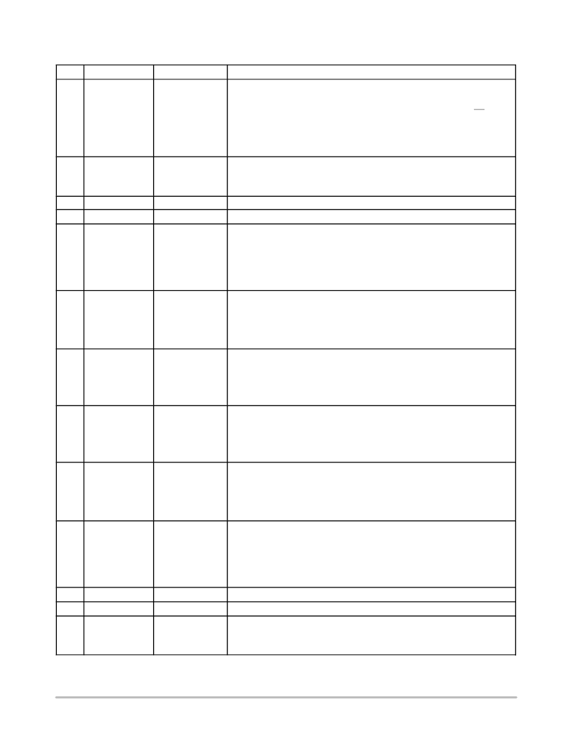
PIN DESCRIPTION
(continued)
Pin
Description
Type
Symbol
24
CRD_IO_A
INPUT/OUTPUT
This pin carries the data serial connection between the external smart card #A and
the microcontroller. A built-in bidirectional level shifter is used to adapt the card and
the MCU, regardless of the power supply voltage of each signals.
This pin is biased by a pull up resistor connected to CRD_VCC_A. When CS = High,
the CRD_IO_A holds the previous I/O logic state and resume to a normal operation
when this pin is reactivated.
The pin is hardwired to zero, the bias being provided by the V
CC
supply, when either
the V
CC
voltage drops below 2.7 V, or during the CRD_VCC_A start-up time.
25
PWR_GND
POWER
This pin carries the power current flow coming from the built in DC/DC converters. It
is associated with the external card # A. It must be connected to the system Ground
and care must be observed at PCB layout level to avoid the risk of spike voltages on
the logic lines.
26
L2_A
POWER
Connects one side of the external DC/DC converter inductor #A (Note 1)
27
L1_A
POWER
Connects one side of the external DC/DC converter inductor #A (Note 1).
28
PWR_VCC_A
POWER
This pin is connected to the positive external power supply. The device sustains any
voltage from +2.7 V to +5.5 V. This voltage supplies the NCN6004A internal circuits
and is regulated by the internal DC/DC converter to provide the DC voltage to the
external card. A high quality capacitor must be connected across pin 28 and
PWR_GND, 10 F/6.0 V ceramic X7R or X5R type is recommended.
Note: The voltage present at pin 28 and 33 must be equal to the voltage present at
pin 42.
29
CRD_VCC_A
POWER
This pin provides the power supply to the external smart card #A. The V
CC
voltage is
defined by programming the NCN6004A accordingly. Since the cards have indepen-
dent DC/DC converter, the output voltage can have any value independently from
CARD_B.
A high quality, low ESR capacitor is mandatory to achieve the V
specifications.
Using two 4.7 F/6.0 V ceramic X7R or X5R capacitors in parallel is recommended.
30
CRD_CLK_A
OUTPUT
This pin is connected to the CLK external smart card #A pin. The signal comes from
the built-in frequency divider dedicated to the #A card. The clock is selected and con-
trolled by setting the logic inputs according to Table 1. The slope of the output clock can
be selected between one of the two programmable mode: SLOW or FAST (Table 8).
The pin is hardwired to zero, the bias being provided by the V
supply, when either
the V
CC
voltage drops below 2.7 V, or during the CRD_VCC_A start-up time.
31
CRD_CLK_B
OUTPUT
This pin is connected to the CLK external smart card #B pin. The signal comes from
the built-in frequency divider dedicated to the #B card. The clock is selected and con-
trolled by setting the logic inputs according to Table 1. The slope of the output clock can
be selected between one of the two programmable mode: SLOW or FAST (Table 8).
The pin is hardwired to zero, the bias being provided by the V
CC
supply, when either
the V
CC
voltage drops below 2.7 V, or during the CRD_VCC_B start-up time.
32
CRD_VCC_B
POWER
This pin provides the power supply to the external smart card #B. The V
CC
voltage is
defined by programming the NCN6004A accordingly. Since the cards have indepen-
dent DC/DC converter, the output voltage can have any value independently from
CARD_A.
A high quality, low ESR capacitor is mandatory to achieve the V
CC
specifications.
Using two 4.7 F/6.0 V ceramic X7R or X5R capacitors in parallel is recommended.
33
PWR_VCC_B
POWER
This pin is connected to the positive external power supply. The device sustains any
voltage from +2.7 V to +6.0 V. This voltage supplies the NCN6004A internal circuits
and is regulated by the internal DC/DC converter to provide the DC voltage to the
external card. A high quality capacitor must be connected across pin 33 and
PWR_GND, 10 F/6.0 V ceramic X7R type is recommended.
Note: The voltage present on pin 28 and 33 must be equal to the voltage present on
pin 42
34
L2b
POWER
Connects one side of the external DC/DC converter inductor #B (Note 1).
35
L1b
POWER
Connects one side of the external DC/DC converter inductor #B (Note 1).
36
PWR_GND
POWER
This pin carries the power current flow coming from the built in DC/DC converters. It
is associated with the external card # B. It must be connected to the system Ground
and care must be observed at PCB layout level to avoid the risk of spike voltages on
ááááááááááááááááááááááááááááááááá
á
ááááááááááááááááááááááááááááááááá
ááááááááááááááááááááááááááááááá
from 10 H to 47 H. To achieve the highest yield, the inductor shall have an ESR < 1.0 .
á
相關PDF資料 |
PDF描述 |
|---|---|
| NCN6010DTBR2 | SIM Card Supply and Level Shifter |
| NCN6010 | SIM Card Supply and Level Shifter |
| NCN6010D | SIM Card Supply and Level Shifter |
| NCN6010DTB | SIM Card Supply and Level Shifter |
| NCP100(中文) | Sub 1V Precision Adjustable Shunt Regulator(基準電壓1V的精密可調旁路穩(wěn)壓器) |
相關代理商/技術參數 |
參數描述 |
|---|---|
| NCN6004A/D | 制造商:ONSEMI 制造商全稱:ON Semiconductor 功能描述:Dual SAM/SIM Interface Integrated Circuit |
| NCN6004A_06 | 制造商:ONSEMI 制造商全稱:ON Semiconductor 功能描述:Dual SAM/SIM Interface Integrated Circuit |
| NCN6004AFTBR2 | 功能描述:輸入/輸出控制器接口集成電路 2.7V POS/ATM Smart RoHS:否 制造商:Silicon Labs 產品: 輸入/輸出端數量: 工作電源電壓: 最大工作溫度:+ 85 C 最小工作溫度:- 40 C 安裝風格:SMD/SMT 封裝 / 箱體:QFN-64 封裝:Tray |
| NCN6004AFTBR2G | 功能描述:輸入/輸出控制器接口集成電路 2.7V POS/ATM Smart Card Interface RoHS:否 制造商:Silicon Labs 產品: 輸入/輸出端數量: 工作電源電壓: 最大工作溫度:+ 85 C 最小工作溫度:- 40 C 安裝風格:SMD/SMT 封裝 / 箱體:QFN-64 封裝:Tray |
| NCN6010 | 制造商:ONSEMI 制造商全稱:ON Semiconductor 功能描述:SIM Card Supply and Level Shifter |
發(fā)布緊急采購,3分鐘左右您將得到回復。