- 您現(xiàn)在的位置:買賣IC網(wǎng) > PDF目錄299508 > MPG5374X T-1 3/4 SINGLE COLOR LED, GREEN, 5 mm PDF資料下載
參數(shù)資料
| 型號(hào): | MPG5374X |
| 元件分類: | LED |
| 英文描述: | T-1 3/4 SINGLE COLOR LED, GREEN, 5 mm |
| 封裝: | ROHS COMPLIANT PACKAGE-2 |
| 文件頁數(shù): | 9/32頁 |
| 文件大?。?/td> | 413K |
| 代理商: | MPG5374X |
第1頁第2頁第3頁第4頁第5頁第6頁第7頁第8頁當(dāng)前第9頁第10頁第11頁第12頁第13頁第14頁第15頁第16頁第17頁第18頁第19頁第20頁第21頁第22頁第23頁第24頁第25頁第26頁第27頁第28頁第29頁第30頁第31頁第32頁
17
XMEGA C3 [DATASHEET]
8361D–AVR–07/2013
9.
Event System
9.1
Features
System for direct peripheral-to-peripheral communication and signaling
Peripherals can directly send, receive, and react to peripheral events
– CPU and DMA controller independent operation
– 100% predictable signal timing
– Short and guaranteed response time
Four event channels for up to four different and parallel signal routing configurations
Events can be sent and/or used by most peripherals, clock system, and software
Additional functions include
– Quadrature decoders
– Digital filtering of I/O pin state
Works in active mode and idle sleep mode
9.2
Overview
The event system enables direct peripheral-to-peripheral communication and signaling. It allows a change in one
peripheral’s state to automatically trigger actions in other peripherals. It is designed to provide a predictable system for
short and predictable response times between peripherals. It allows for autonomous peripheral control and interaction
without the use of interrupts, CPU, or DMA controller resources, and is thus a powerful tool for reducing the complexity,
size and execution time of application code. It also allows for synchronized timing of actions in several peripheral
modules.
A change in a peripheral’s state is referred to as an event, and usually corresponds to the peripheral’s interrupt
conditions. Events can be directly passed to other peripherals using a dedicated routing network called the event routing
network. How events are routed and used by the peripherals is configured in software.
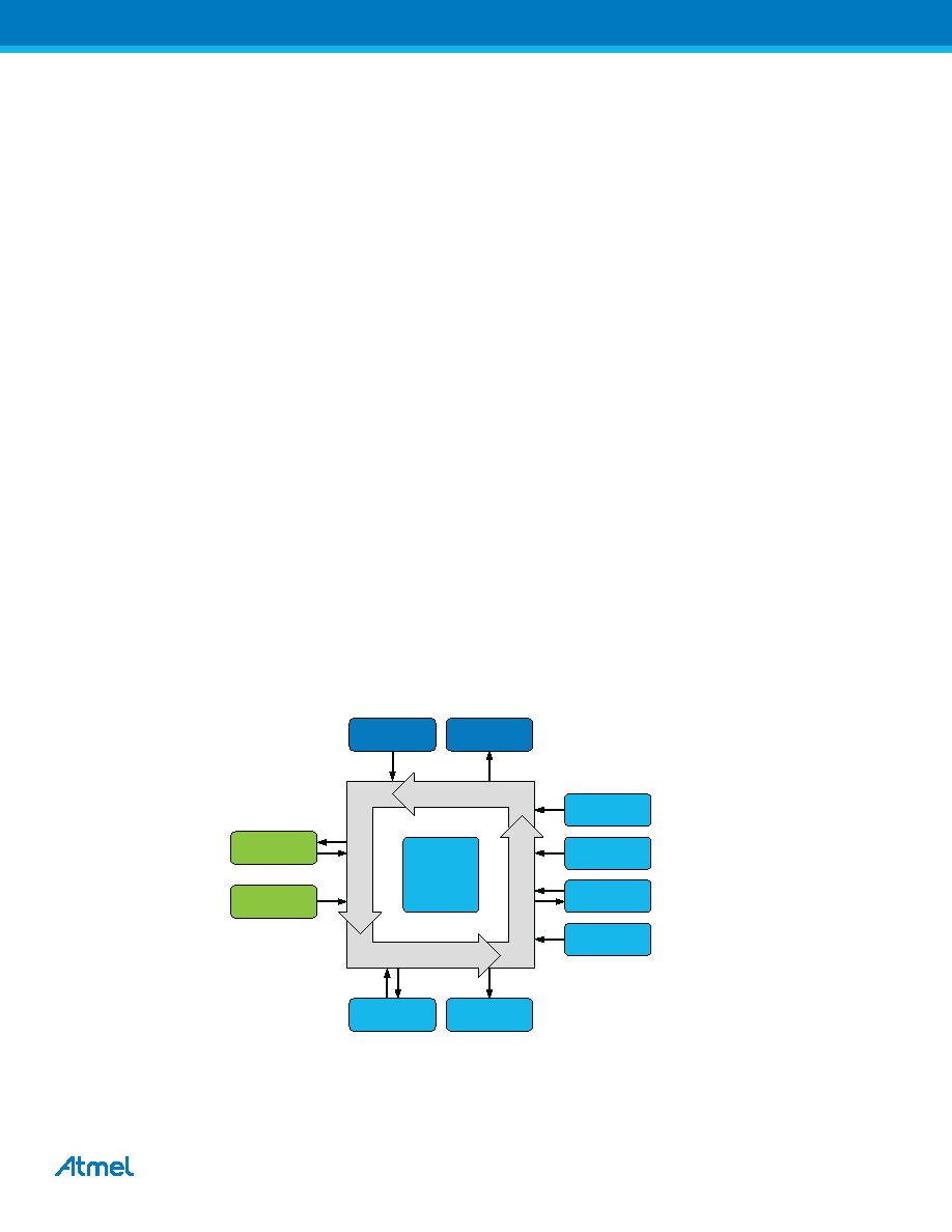
Figure on page 17 shows a basic diagram of all connected peripherals. The event system can directly connect together
analog to digital converter, analog comparators, I/O port pins, the real-time counter, timer/counters, IR communication
module (IRCOM), and USB interface. It can also be used to trigger DMA transactions (DMA controller). Events can also
be generated from software and the peripheral clock.
Figure 9-1. Event system overview and connected peripherals.
The event routing network consists of four software-configurable multiplexers that control how events are routed and
used. These are called event channels, and allow for up to four parallel event routing configurations. The maximum
routing latency is two peripheral clock cycles. The event system works in both active mode and idle sleep mode.
Timer /
Counters
USB
ADC
Real Time
Counter
Port pins
CPU /
Software
DMA
Controller
IRCOM
Event Routing Network
Event
System
Controller
clkPER
Prescaler
AC
相關(guān)PDF資料 |
PDF描述 |
|---|---|
| MPI002/TERM/RD | PUSHBUTTON SWITCH, SPST, MOMENTARY-TACTILE, 0.05A, 24VDC, PANEL MOUNT |
| MPN-7430 | 300 V, SILICON, PIN DIODE |
| MPR3372X | T-1 SINGLE COLOR LED, RED, 3 mm |
| MPS101A | SLIDE SWITCH, SP3T, LATCHED, 0.3A, 30VDC, THROUGH HOLE-RIGHT ANGLE |
| MPS3414 | NPN SILICON TRANSISTOR |
相關(guān)代理商/技術(shù)參數(shù) |
參數(shù)描述 |
|---|---|
| MPG5379K | 制造商:Stanley Electric Co 功能描述:LED Uni-Color Green 560nm 2-Pin Bulk 制造商:The Stanley Works 功能描述:Green 2.5 x 5 mm 24 x 18 Min 12 mcd Typical 24 mcd Diffused Through Hole LED 制造商:STANLEY 功能描述:Green 2.5 x 5 mm 24 ? x 18 ? Min 12 mcd Typical 24 mcd Diffused Through Hole LED 制造商:Stanley Electric Co 功能描述:Green 2.5 x 5 mm 24 ? x 18 ? Min 12 mcd Typical 24 mcd Diffused Through Hole LED |
| MPG5763X | 制造商:未知廠家 制造商全稱:未知廠家 功能描述:Optoelectronic |
| MPG5764X | 制造商:未知廠家 制造商全稱:未知廠家 功能描述:Optoelectronic |
| MPG5773X | 制造商:未知廠家 制造商全稱:未知廠家 功能描述:Optoelectronic |
| MPG5774X | 制造商:未知廠家 制造商全稱:未知廠家 功能描述:Optoelectronic |
發(fā)布緊急采購,3分鐘左右您將得到回復(fù)。