- 您現(xiàn)在的位置:買賣IC網(wǎng) > PDF目錄45352 > MPC603RZT233TX (MOTOROLA INC) 32-BIT, 233 MHz, RISC PROCESSOR, PBGA255 PDF資料下載
參數(shù)資料
| 型號: | MPC603RZT233TX |
| 廠商: | MOTOROLA INC |
| 元件分類: | 微控制器/微處理器 |
| 英文描述: | 32-BIT, 233 MHz, RISC PROCESSOR, PBGA255 |
| 封裝: | 23 X 23 MM, 2.60 MM HEIGHT, 1.27 MM PITCH, PLASTIC, BGA-255 |
| 文件頁數(shù): | 16/36頁 |
| 文件大小: | 440K |
| 代理商: | MPC603RZT233TX |
第1頁第2頁第3頁第4頁第5頁第6頁第7頁第8頁第9頁第10頁第11頁第12頁第13頁第14頁第15頁當(dāng)前第16頁第17頁第18頁第19頁第20頁第21頁第22頁第23頁第24頁第25頁第26頁第27頁第28頁第29頁第30頁第31頁第32頁第33頁第34頁第35頁第36頁
PID7t-603e Hardware Specifications
23
System Design Information
1.8 System Design Information
This section provides electrical and thermal design recommendations for successful application of the 603e.
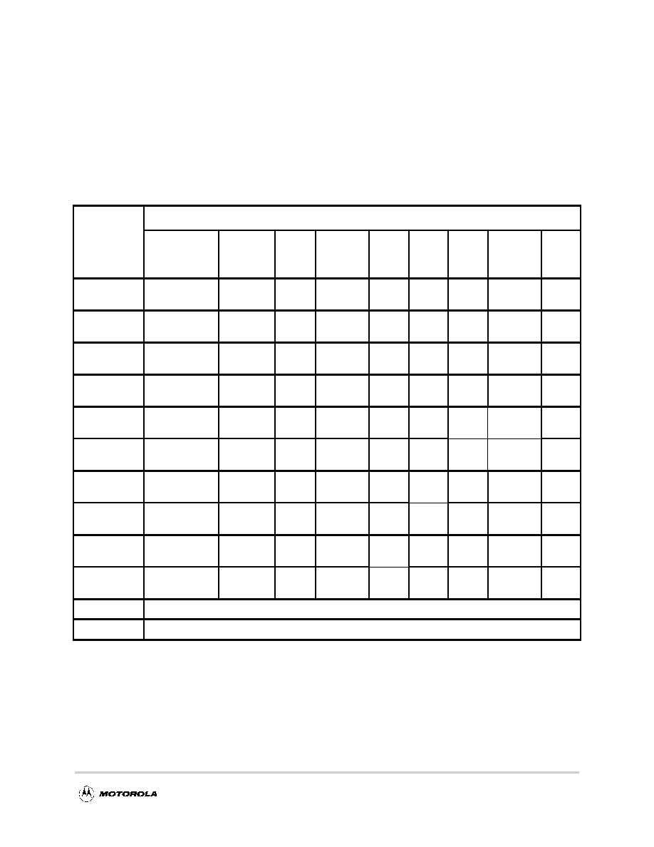
1.8.1 PLL Conguration
The 603e PLL is congured by the PLL_CFG[03] signals. For a given SYSCLK (bus) frequency, the PLL
conguration signals set the internal CPU and VCO frequency of operation. The PLL conguration for the
PID7t-603e is shown in Table 12 for nominal frequencies.
Table 12. PLL Configuration
PLL_CFG[0:3]
CPU Frequency in MHz (VCO Frequency in MHz)
Bus-to-Core
Multiplier
Core-to
VCO
Multiplier
Bus
25 MHz
Bus
33.33 MHz
Bus
40 MHz
Bus
50 MHz
Bus
60 MHz
Bus
66.67 MHz
Bus
75 MHz
0100
2x
—
————
150
(300)
0101
2x
4x
—
804
(320)
100
(400)
120
(480)
133
(532)
150
(600)
0110
2.5x
2x
—
150
(300)
166
(333)
187
(375)
1000
3x
2x
—
150
(300)
180
(360)
200
(400)
225
(450)
1110
3.5x
2x
—
175
(350)
210
(420)
233 (466)
263
(525)
1010
4x
2x
—
160
(320)
200
(400)
240
(480)
267 (533)
300
(600)
0111
4.5x
2x
—
150
(300)
180
(360)
225
(450)
270
(540)
300 (600)
—
1011
5x
2x
—
166
(333)
200
(400)
250
(500)
300
(600)
——
1001
5.5x
2x
—
183 (366)
220
(440)
275
(550)
——
—
1101
6x
2x
150
(300)
200
(400)
240
(480)
300
(600)
——
—
0011
PLL bypass
1111
Clock off
Notes:
1. Some PLL congurations may select bus, CPU, or VCO frequencies which are not supported; see
Section 1.4.2.1, “Clock AC Specications,” for valid SYSCLK and VCO frequencies.
2. In PLL-bypass mode, the SYSCLK input signal clocks the internal processor directly, the PLL is disabled, and
the bus mode is set for 1:1 mode operation. This mode is intended for factory use only.
Note: The AC timing specications given in this document do not apply in PLL-bypass mode.
3. In clock-off mode, no clocking occurs inside the 603e regardless of the SYSCLK input.
4. 80 MHz operation is not supported for the PBGA package (see Table 7)
相關(guān)PDF資料 |
PDF描述 |
|---|---|
| MPC604ERX200 | 32-BIT, 200 MHz, RISC PROCESSOR, CBGA256 |
| MPC604ERX350 | 32-BIT, 350 MHz, RISC PROCESSOR, CBGA256 |
| MPC604ERX333 | 32-BIT, 333 MHz, RISC PROCESSOR, CBGA256 |
| MPC604ERX250 | 32-BIT, 250 MHz, RISC PROCESSOR, CBGA256 |
| MPC7400RX333LX | 32-BIT, 333 MHz, RISC PROCESSOR, CBGA360 |
相關(guān)代理商/技術(shù)參數(shù) |
參數(shù)描述 |
|---|---|
| MPC604E | 制造商:MOTOROLA 制造商全稱:Motorola, Inc 功能描述:PowerPC 604e-TM RISC Microprocessor Technical Summary |
| MPC6071 | 制造商:International Rectifier 功能描述: |
| MPC616 | 制造商:Hammond Manufacturing 功能描述:6" X 16" MAGNET PANEL COVER |
| MPC-628-011B | 制造商:FCI 功能描述: |
| MPC628726C | 制造商:FCI 功能描述:- Bulk |
發(fā)布緊急采購,3分鐘左右您將得到回復(fù)。