- 您現(xiàn)在的位置:買賣IC網(wǎng) > PDF目錄359132 > MC33389 (飛思卡爾半導(dǎo)體(中國)有限公司) System Basis Chip with Low Speed Fault Tolerant CAN(帶低速容錯(cuò)CAN接口的系統(tǒng)基片) PDF資料下載
參數(shù)資料
| 型號(hào): | MC33389 |
| 廠商: | 飛思卡爾半導(dǎo)體(中國)有限公司 |
| 英文描述: | System Basis Chip with Low Speed Fault Tolerant CAN(帶低速容錯(cuò)CAN接口的系統(tǒng)基片) |
| 中文描述: | 系統(tǒng)基礎(chǔ)芯片與低速容錯(cuò)CAN(帶低速容錯(cuò)的CAN接口的系統(tǒng)基片) |
| 文件頁數(shù): | 31/35頁 |
| 文件大小: | 591K |
| 代理商: | MC33389 |
第1頁第2頁第3頁第4頁第5頁第6頁第7頁第8頁第9頁第10頁第11頁第12頁第13頁第14頁第15頁第16頁第17頁第18頁第19頁第20頁第21頁第22頁第23頁第24頁第25頁第26頁第27頁第28頁第29頁第30頁當(dāng)前第31頁第32頁第33頁第34頁第35頁
MC33389
31
MC33389
Sleep Mode Activation
Once in sleep mode, the SBC turns off V1 and V2
regulator. Thus the micro controller can not run any mode.
in order to have it run again, the SBC should enable and
turn on V1, and this is achieve by an SBC wake up event.
Several options are available to wake up the SBC and the
application and have the micro controller in run mode.
Some wake up are selectable, some are always active in
sleep mode.
- Wake up from CAN interface and wake up from SPI
(CSB) are always active.
- Wake up from L0/L1/L2 inputs, with and without cyclic
sense and the FWU (Forced Wake Up) are selectable. The
selection must be done while the SBC is in Normal or Standby
mode, and prior to enter sleep mode.
General Condition To Enter Sleep Mode
In order to make sure the SBC enters the sleep mode, and
in addition to the write into MCR and MCVR register, all
previous wake up conditions must have been cleared. To
clear a wake up condition requires that the appropriate
register is read.
After an SBC power up from “zero” (battery power up or
cold start), the following registers must be read:
- WUICR: possible wake up event report from CAN bus
- RSR: report a V1 undervoltage
- VSSR: reports a Vbat fail flag
Once these read operation are done, the wake up
conditions or flag are reset.
The VSSR register bit VBSR0 can be used to determined
if the SBC has experience a loss of battery voltage.
After an SBC wake up from “sleep mode” the following
registers indicate the wake up source and must be cleared in
order to allow the SBC to enter sleep mode again:
- WUICR: wake up event report for CAN or SPI buses.
- WUISR: Wake up event report for the L0/L1/L2 inputs.
- RSR: report a V1 undervoltage
- VSSR: reports a Vbat fail flag
- etc
The paragraphs below describe the write operation to be
done for the several sleep mode and wake up control options.
In addition to FWU, cyclic sense and direct wake up, the
CAN and SPI wake will always be activated.
Sleep Mode With CAN And SPI Wake Up
The enter sleep mode and activate the only the CAN or
SPI wake up, no dedicated wake up condition must be done.
In sleep mode the SBC has CAN and SPI wake up always
active. To enter sleep mode in this case, while the SBC is in
normal or standby mode:
- Write to V3R register: data 0000 (this clear the bit WI2V3
which is set to1 after reset).
- Write to MCR register: data SLEEP (100)
- Write to MCVR register: data SLEEP (100)
The SBC then enters sleep mode.
Sleep Mode Enter With Forced Wake Up
To enter sleep mode and activate the forced wake up the
following register must be written:
- Write to V3R register, data 0100), this set the FWU bit to 1.
- Write to CYTCR register the desired wake up time. (This
sets the time the SBC will stay in sleep mode).
- Write to MCR register: data SLEEP (100)
- Write to MCVR register: data SLEEP (100)
The SBC then enters sleep mode. It will wake up after the
time period selected in the CYTCR register.
Sleep Mode Enter With Cyclic Sense
To enter sleep mode and activate the cyclic sense wake
up the following register must be written:
- Write to V3R register, data 1010, this set the VI2V3 and
CYS bits to 1.
- Write to CYTCR register the desired cyclic sense period.
(This sets the time the SBC will wait in sleep mode to turn on
V3 and sense the Lx inputs).
- Write to WUICR bits 0 and 1 to select the edge sensitivity
for the Lx inputs.
- Write to MCR register: data SLEEP (100)
- Write to MCVR register: data SLEEP (100)
The SBC then enters sleep mode. It will periodically turn
on V3 and while V3 is on, sample the level of the Ls inputs.
If any of the 3 Lx inputs is in the correct state for two
consecutive samples, SBC will wake up. If not, it will stay in
sleep mode. (refer to device description for detail).
Sleep Mode Enter With Direct Lx Input Wake Up
To enter sleep mode and activate the direct wake up from
the Lx inputs, the following register must be written:
- Write to V3R register, data 0000), this clear VI2V3 bit.
- Write to WUICR bits 0 and 1 to select the edge sensitivity
for the Lx inputs.
- Write to MCR register: data SLEEP (100)
- Write to MCVR register: data SLEEP (100)
The SBC then enters sleep mode. It will wake up as soon
as any of the Lx input read the correct state.
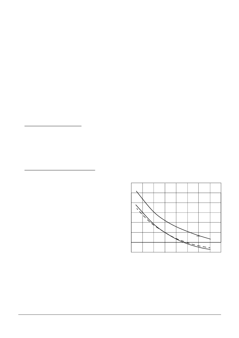
Figure 59. Typical Sleep Current vs Temp and Batt
Voltage
40
100
60
120
80
140
T
16V
TEMPERATURE (°C)
-50
0
50
100
150
-25
25
75
125
160
180
12V
6V
F
Freescale Semiconductor, Inc.
For More Information On This Product,
Go to: www.freescale.com
n
.
相關(guān)PDF資料 |
PDF描述 |
|---|---|
| MC33390 | J-1850 SERIAL TRANSCEIVER(串行J-1850總線收發(fā)器) |
| MC33394 | Switch Mode Power Supply with Multiple Linear Regulators and High Speed CAN Transceiver(帶有多個(gè)線性穩(wěn)壓器和高速CAN收發(fā)器的開關(guān)方式電源) |
| MC33395 | Three-Phase Gate Driver IC(3相柵極驅(qū)動(dòng)器) |
| MC33397 | Dual/Hex Low-Side Switch with Both SPI and Parallel Input Control(帶SPI和并口輸入控制的2或6低端開關(guān)) |
| MC33399 | “Local Interconnect Network” Physical Interface(“本地互聯(lián)網(wǎng)”(LIN)物理接口) |
相關(guān)代理商/技術(shù)參數(shù) |
參數(shù)描述 |
|---|---|
| MC33389CDH | 功能描述:IC SYSTEM BASIS W/CAN 20-HSOP RoHS:是 類別:集成電路 (IC) >> 接口 - 控制器 系列:- 標(biāo)準(zhǔn)包裝:4,900 系列:- 控制器類型:USB 2.0 控制器 接口:串行 電源電壓:3 V ~ 3.6 V 電流 - 電源:135mA 工作溫度:0°C ~ 70°C 安裝類型:表面貼裝 封裝/外殼:36-VFQFN 裸露焊盤 供應(yīng)商設(shè)備封裝:36-QFN(6x6) 包裝:* 其它名稱:Q6396337A |
| MC33389CDHR2 | 功能描述:IC SYSTEM BASE W/CAN 20-HSOP RoHS:是 類別:集成電路 (IC) >> 接口 - 控制器 系列:- 標(biāo)準(zhǔn)包裝:4,900 系列:- 控制器類型:USB 2.0 控制器 接口:串行 電源電壓:3 V ~ 3.6 V 電流 - 電源:135mA 工作溫度:0°C ~ 70°C 安裝類型:表面貼裝 封裝/外殼:36-VFQFN 裸露焊盤 供應(yīng)商設(shè)備封裝:36-QFN(6x6) 包裝:* 其它名稱:Q6396337A |
| MC33389CDW | 功能描述:網(wǎng)絡(luò)控制器與處理器 IC SYSTEM BASIC CHIPS RoHS:否 制造商:Micrel 產(chǎn)品:Controller Area Network (CAN) 收發(fā)器數(shù)量: 數(shù)據(jù)速率: 電源電流(最大值):595 mA 最大工作溫度:+ 85 C 安裝風(fēng)格:SMD/SMT 封裝 / 箱體:PBGA-400 封裝:Tray |
| MC33389CDWR2 | 功能描述:網(wǎng)絡(luò)控制器與處理器 IC SYSTEM BASIC CHIPS RoHS:否 制造商:Micrel 產(chǎn)品:Controller Area Network (CAN) 收發(fā)器數(shù)量: 數(shù)據(jù)速率: 電源電流(最大值):595 mA 最大工作溫度:+ 85 C 安裝風(fēng)格:SMD/SMT 封裝 / 箱體:PBGA-400 封裝:Tray |
| MC33389DDW | 功能描述:網(wǎng)絡(luò)控制器與處理器 IC SBC SOW28 RoHS:否 制造商:Micrel 產(chǎn)品:Controller Area Network (CAN) 收發(fā)器數(shù)量: 數(shù)據(jù)速率: 電源電流(最大值):595 mA 最大工作溫度:+ 85 C 安裝風(fēng)格:SMD/SMT 封裝 / 箱體:PBGA-400 封裝:Tray |
發(fā)布緊急采購,3分鐘左右您將得到回復(fù)。