- 您現(xiàn)在的位置:買賣IC網(wǎng) > PDF目錄378659 > MC145191DT (MOTOROLA INC) 1.1 GHz PLL Frequency Synthesizers PDF資料下載
參數(shù)資料
| 型號(hào): | MC145191DT |
| 廠商: | MOTOROLA INC |
| 元件分類: | XO, clock |
| 英文描述: | 1.1 GHz PLL Frequency Synthesizers |
| 中文描述: | PLL FREQUENCY SYNTHESIZER, 1100 MHz, PDSO20 |
| 封裝: | TSSOP-20 |
| 文件頁數(shù): | 1/24頁 |
| 文件大?。?/td> | 341K |
| 代理商: | MC145191DT |
MC145190
MC145191
MOTOROLA
1
Include On–Board 64/65 Prescalers
The MC145190 and MC145191 are single–package synthesizers with serial
interfaces capable of direct usage up to 1.1 GHz. A special architecture makes
these PLLs very easy to program because a byte–oriented format is utilized.
Due to the patented BitGrabber
registers, no address/steering bits are
required for randomaccessof the three registers. Thus, tuning can be
accomplished via a 3–byte serial transfer to the 24–bit A register. The interface
is both SPI and MICROWIRE
compatible.
Each device features a single–ended current source/sink phase detector
output and a double–ended phase detector output. Both phase detectors have
linear transfer functions (no dead zones). The maximum current of the
single–ended phase detector output is determined by an external resistor tied
from the Rx pin to ground. This current can be varied via the serial port.
The MC145190 features logic–level converters and high–voltage phase/
frequency detectors; the detector supply may range up to 9.5 V. The
MC145191 has lower–voltage phase/frequency detectors optimized for
single–supply systems of 5 V
±
10%.
Each part includes a differential RF input which may be operated in a
single–ended mode. Also featured are on–board support of an external crystal
and a programmable reference output. The R, A, and N counters are fully
programmable. The C register (configuration register) allows the parts to be
configured to meet various applications. A patented feature allows the C
register to shut off unused outputs, thereby minimizing system noise and
interference.
In order to have consistent lock times and prevent erroneous data from being
loaded into the counters, on–board circuitry synchronizes the update of the A
register if the A or N counters are loading. Similarly, an update of the R register
is synchronized if the R counter is loading.
The double–buffered R register allows new divide ratios to be presented to
the three counters (R, A, and N) simultaneously.
Maximum Operating Frequency: 1100 MHz @ Vin = 200 mV p–p
Operating Supply Current: 7 mA Nominal
Operating Supply Voltage Range (VDD and VCC Pins): 4.5 to 5.5 V
Operating Supply Voltage Range of Phase Detectors (VPD Pin) —
MC145190: 8.0 to 9.5 V
MC145191: 4.5 to 5.5 V
Current Source/Sink Phase Detector OUTPUT Capability: 2 mA Maximum
Gain of Current Source/Sink Phase/Frequency Detector Controllable via
Serial Port
Operating Temperature Range: – 40 to + 85
°
C
R Counter Division Range: (1 and) 5 to 8191
Dual–Modulus Capability Provides Total Division up to 262,143
High–Speed Serial Interface: 4 Mbps
OUTPUT A Pin, When Configured as Data Out, Permits Cascading of Devices
Two General–Purpose Digital Outputs — OUTPUT A: Totem–Pole (Push–Pull)
OUTPUT B: Open–Drain
Patented Power–Saving Standby Feature with Orderly Recovery for
Minimizing Lock Times, Standby Current: 30
μ
A
Evaluation Kit Available (Part Numbers MC145190EVK and MC145191EVK)
See Application Note AN1253/D for Low–Pass Filter Design, and
AN1277/D for Offset Reference PLLs for Fine Resolution or Fast Hopping
BitGrabber is a trademark of Motorola Inc. MICROWIRE is a trademark of National Semiconductor Corp.
Order this document
by MC145190/D
SEMICONDUCTOR TECHNICAL DATA
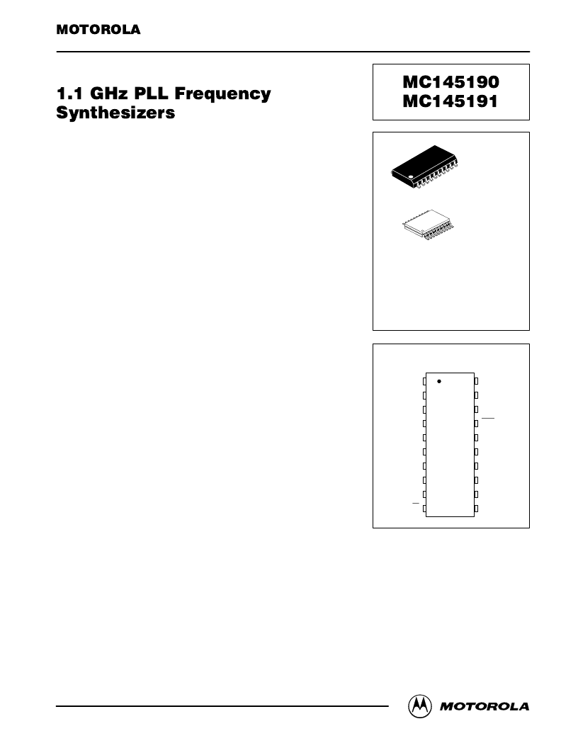
fin
TEST 2
OUTPUT B
OUTPUT A
CLK
12
13
14
15
16
11
10
Din
REFin
VCC
ENB
8
7
6
5
4
3
2
1
TEST 1
Rx
GND
PDout
φ
V
φ
R
LD
REFout
9
18
19
20
17
PIN ASSIGNMENT
VPD
fin
VDD
F SUFFIX
SOG
PACKAGE
CASE 751J
ORDERING INFORMATION
MC145190F
MC145191F
SOG Package
SOG Package
MC145190DT
MC145191DT
TSSOP
TSSOP
20
1
DT SUFFIX
TSSOP
CASE 948D
20
1
REV 5
1/98 TN98012300
相關(guān)PDF資料 |
PDF描述 |
|---|---|
| MC145191F | 1.1 GHz PLL Frequency Synthesizers |
| MC145192DT | 8-Pin High Frequency 4-Amp Sink Synchronous MOSFET Driver 8-SOIC -40 to 125 |
| MC145192 | Low-Voltage 1.1 GHz PLL Frequency Synthesizer |
| MC145192EVK | 8-Pin High Frequency 4-Amp Sink Synchronous MOSFET Driver 8-SON -40 to 125 |
| MC145192F | Low-Voltage 1.1 GHz PLL Frequency Synthesizer |
相關(guān)代理商/技術(shù)參數(shù) |
參數(shù)描述 |
|---|---|
| MC14519BCL | 制造商:Motorola Inc 功能描述: 制造商:Motorola Inc 功能描述:LOGIC MUX, QUAD, 2-INPUT, CMOS, 16 Pin, Ceramic, DIP |
| MC14519BD | 制造商:Rochester Electronics LLC 功能描述:- Bulk |
| MC14519BF | 制造商:Panasonic Industrial Company 功能描述:IC |
| MC1451CCP | 制造商:PMD 功能描述: |
| MC14520B | 制造商:Motorola Inc 功能描述: 制造商:ON Semiconductor 功能描述: |
發(fā)布緊急采購(gòu),3分鐘左右您將得到回復(fù)。