- 您現(xiàn)在的位置:買賣IC網(wǎng) > PDF目錄9499 > MAX1407CAI+ (Maxim Integrated Products)IC DAS 16BIT LP 28-SSOP PDF資料下載
參數(shù)資料
| 型號: | MAX1407CAI+ |
| 廠商: | Maxim Integrated Products |
| 文件頁數(shù): | 26/48頁 |
| 文件大小: | 0K |
| 描述: | IC DAS 16BIT LP 28-SSOP |
| 產(chǎn)品培訓(xùn)模塊: | Lead (SnPb) Finish for COTS Obsolescence Mitigation Program |
| 標(biāo)準(zhǔn)包裝: | 46 |
| 類型: | 數(shù)據(jù)采集系統(tǒng)(DAS) |
| 分辨率(位): | 16 b |
| 采樣率(每秒): | 60 |
| 數(shù)據(jù)接口: | 串行 |
| 電壓電源: | 模擬和數(shù)字 |
| 電源電壓: | 2.7 V ~ 3.6 V |
| 工作溫度: | 0°C ~ 70°C |
| 安裝類型: | 表面貼裝 |
| 封裝/外殼: | 28-SSOP(0.209",5.30mm 寬) |
| 供應(yīng)商設(shè)備封裝: | 28-SSOP |
| 包裝: | 管件 |
第1頁第2頁第3頁第4頁第5頁第6頁第7頁第8頁第9頁第10頁第11頁第12頁第13頁第14頁第15頁第16頁第17頁第18頁第19頁第20頁第21頁第22頁第23頁第24頁第25頁當(dāng)前第26頁第27頁第28頁第29頁第30頁第31頁第32頁第33頁第34頁第35頁第36頁第37頁第38頁第39頁第40頁第41頁第42頁第43頁第44頁第45頁第46頁第47頁第48頁

MAX1407/MAX1408/MAX1409/MAX1414
Low-Power, 16-Bit Multichannel DAS with
Internal Reference,10-Bit DACs, and RTC
32
______________________________________________________________________________________
WE: Write Enable bit. WE must be set to “1” before any
write operation to the clock and the alarm register. A
logic 0 disables write operations to the clock and alarm
registers, including the AE bit. The WE signal takes
effect after the 8th SCLK rising edge for an 8-bit write.
AE: Alarm Enable bit. A logic 0 disables the alarm func-
tion. When AE equals “1”, the ALIRQ bit in the Al_Status
register will be set to 1 whenever the current time
matches that of the alarm registers.
Real-Time Clock (RTC)
The RTC_Sec, RTC_Min, RTC_Hour, RTC_Date,
RTC_Month, RTC_Day, RTC_Year, and RTC_Century
registers can be accessed one register at a time or in
Burst mode (see RTC_BURST REGISTER section). The
RTC runs continuously and does not stop for read or
write operations. To prevent the data from changing
during a read operation, complete all read operations
on the RTC registers (single register reads and burst
reads) in less than 1ms.
Using single reads to read all the RTC registers could
lead to errors as much as a century. Since the registers
are updated between read operations, the register con-
tents may change before all RTC registers have been
read, when reading one register at a time. The most
accurate way to get the time information of the RTC
registers is with a burst read. In the burst read, a snap-
shot of the eight RTC registers (RTC_Sec, RTC_Min,
RTC_Hour, RTC_Date, RTC_Month, RTC_Day,
RTC_Year, RTC_Century) is taken once and read
sequentially with the MSB of the Seconds register first.
They must all be read out as a group of eight registers
of eight bits each, for proper execution of the burst
read function. The worst-case error that can occur
between the “actual” time and the “reported” time is
one second. As with a read operation, using single
writes to update the RTC can lead to collisions. To
guarantee an accurate update of the RTC, use the
Burst Write mode (see Alarm and RTC Programming
section).
The RTC defaults to 24-hr mode, 00:00:00, Sunday,
January 01, 1970 during power-up. January 01, 1970
falls on a Thursday, but since this RTC is not time-
based, the default values do not have an impact on the
functionality of the clock, and they merely provide some
means for testing. If the alarm or RTC registers are pro-
grammed to some unused states, the device chooses
the default values.
RTC_BURST REGISTER (01111)
Writing to this address begins the burst mode transfer.
In this mode, all the real-time clock registers are contin-
uously read or written starting with Bit 7 of the
RTC_Sec,
RTC_Min,
RTC_Hour,
RTC_Date,
RTC_Month, RTC_Day, RTC_Year, and RTC_Century
registers. When reading, the contents of DIN will be
ignored and each register’s 8-bit data will be clocked
out at DOUT on the falling edge of SCLK (total of 64
clock cycles). When writing, start with the Seconds’
register MSB first and continue through the Century
register (see Alarm and RTC Programming section).
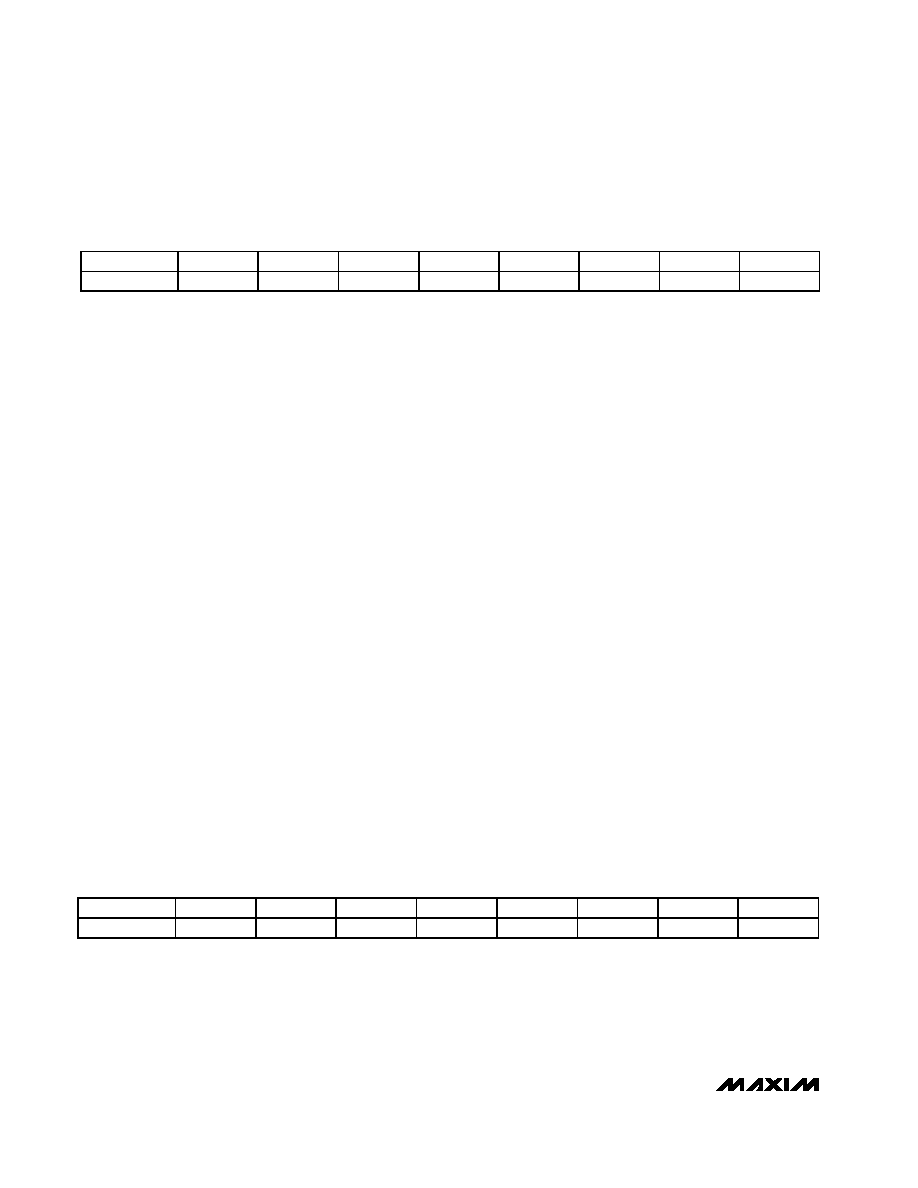
ALARM/CLOCK_CTRL REGISTER (01110)
FIRST BIT (MSB)
(LSB)
NAME
WE
—————
—
AE
DEFAULT
000000
00
CH: Clock Halt bit. Writing a “1” to CH disables the
real-time clock and oscillator.
10SEC[2:0]: These are the 10 second bits (10–50 sec-
onds) of the RTC.
SEC[3:0]: These are the second bits (0–9 seconds) of
the RTC.
FIRST BIT (MSB)
(LSB)
NAME
CH
10SEC2
10SEC1
10SEC0
SEC3
SEC2
SEC1
SEC0
DEFAULT
0
RTC_SEC REGISTER (10000)
相關(guān)PDF資料 |
PDF描述 |
|---|---|
| MAX1414CAI+ | IC DAS 16BIT LP 28-SSOP |
| NBXDPA019LN1TAG | IC CLK XO LVDS 125/250MHZ 6CLCC |
| MAX181CCQH+D | IC DAS 12BIT 100KSPS 44-PLCC |
| 74AC138SC | IC DECODER/DEMUX 1OF8 16-SOIC |
| MAX181CCQH-D | IC DAS 6CH 12BIT 100KHZ 44-PLCC |
相關(guān)代理商/技術(shù)參數(shù) |
參數(shù)描述 |
|---|---|
| MAX1407CAI+ | 功能描述:ADC / DAC多通道 16-Bit 4Ch 60sps 1.35V Precision ADC RoHS:否 制造商:Texas Instruments 轉(zhuǎn)換速率: 分辨率:8 bit 接口類型:SPI 電壓參考: 電源電壓-最大:3.6 V 電源電壓-最小:2 V 最大工作溫度:+ 85 C 安裝風(fēng)格:SMD/SMT 封裝 / 箱體:VQFN-40 |
| MAX1407CAI+T | 功能描述:ADC / DAC多通道 16-Bit 4Ch 60sps 1.35V Precision ADC RoHS:否 制造商:Texas Instruments 轉(zhuǎn)換速率: 分辨率:8 bit 接口類型:SPI 電壓參考: 電源電壓-最大:3.6 V 電源電壓-最小:2 V 最大工作溫度:+ 85 C 安裝風(fēng)格:SMD/SMT 封裝 / 箱體:VQFN-40 |
| MAX1407CAI-T | 功能描述:ADC / DAC多通道 RoHS:否 制造商:Texas Instruments 轉(zhuǎn)換速率: 分辨率:8 bit 接口類型:SPI 電壓參考: 電源電壓-最大:3.6 V 電源電壓-最小:2 V 最大工作溫度:+ 85 C 安裝風(fēng)格:SMD/SMT 封裝 / 箱體:VQFN-40 |
| MAX1407EAI+ | 制造商:Maxim Integrated Products 功能描述:LOW-POWER 16-BIT MULTICHANNEL DAS - Rail/Tube |
| MAX1407EAI+T | 制造商:Maxim Integrated Products 功能描述:LOW-POWER 16-BIT MULTICHANNEL DAS - Tape and Reel |
發(fā)布緊急采購,3分鐘左右您將得到回復(fù)。