- 您現(xiàn)在的位置:買賣IC網 > PDF目錄370847 > M37702S1BFP (Mitsubishi Electric Corporation) Single Chip 16 Bits CMOS Microcomputer(16位單片機) PDF資料下載
參數(shù)資料
| 型號: | M37702S1BFP |
| 廠商: | Mitsubishi Electric Corporation |
| 英文描述: | Single Chip 16 Bits CMOS Microcomputer(16位單片機) |
| 中文描述: | 單片微機16位的CMOS(16位單片機) |
| 文件頁數(shù): | 35/59頁 |
| 文件大?。?/td> | 811K |
| 代理商: | M37702S1BFP |
第1頁第2頁第3頁第4頁第5頁第6頁第7頁第8頁第9頁第10頁第11頁第12頁第13頁第14頁第15頁第16頁第17頁第18頁第19頁第20頁第21頁第22頁第23頁第24頁第25頁第26頁第27頁第28頁第29頁第30頁第31頁第32頁第33頁第34頁當前第35頁第36頁第37頁第38頁第39頁第40頁第41頁第42頁第43頁第44頁第45頁第46頁第47頁第48頁第49頁第50頁第51頁第52頁第53頁第54頁第55頁第56頁第57頁第58頁第59頁

35
MITSUBISHI MICROCOMPUTERS
M37702M2AXXXFP, M37702M2BXXXFP
M37702S1AFP, M37702S1BFP
SINGLE-CHIP 16-BIT CMOS MICROCOMPUTER
(1) One-shot mode [00]
The A-D conversion pins are selected with the bit 0 to 2 of A-D
control register. A-D conversion can be started by a software trig-
ger or by an external trigger.
A software trigger is selected when the bit 5 of A-D control register
is “0” and an external trigger is selected when it is “1”.
When a software trigger is selected, A-D conversion is started
when bit 6 (A-D conversion start flag) is set. A-D conversion ends
after 57
φ
AD
cycles and an interrupt request bit is set in the A-D
conversion interrupt control register. At the same time, A-D control
register bit 6 (A-D conversion start flag) is cleared and A-D con-
version stops. The result of A-D conversion is stored in the A-D
register corresponding to the selected pin.
If an external trigger is selected, A-D conversion starts when the
A-D conversion start flag is “1” and the AD
TRG
input changes from
“H” to “L”. In this case, the pins that can be used for A-D conver-
sion are AN
0
to AN
6
because the AD
TRG
pin is shared with the
analog voltage input pin AN
7
. The operation is the same as with
software trigger except that the A-D conversion start flag is not
cleared after A-D conversion and a retrigger can be available dur-
ing A-D conversion.
(2) Repeat mode [01]
The operation of this mode is the same as the operation of one-
shot mode except that when A-D conversion of the selected pin is
complete and the result is stored in the A-D register, conversion
does not stop, but is repeated. Also, no interrupt request is issued
in this mode. Furthermore, if software trigger is selected, the A-D
conversion start flag is not cleared. The contents of the A-D regis-
ter can be read at any time.
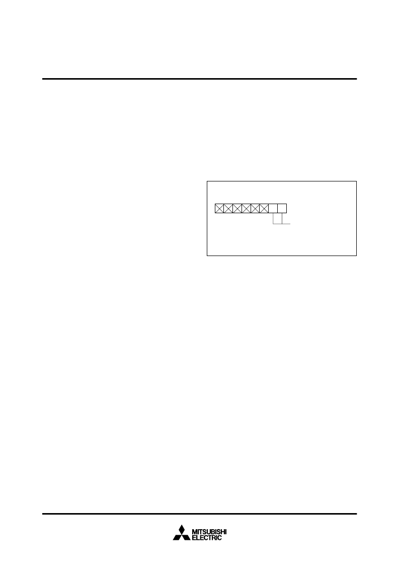
(3) Single sweep mode [10]
In the sweep mode, the number of analog input pins to be swept
can be selected. Analog input pins are selected by bits 1 and 0 of
the A-D sweep pin selection register (1F
16
address) shown in Fig-
ure 45. Two pins, four pins, six pins, or eight pins can be selected
as analog input pins, depending on the contents of these bits.
A-D conversion is performed only for selected input pins. After
A-D conversion is performed for input of AN
0
pin, the conversion
result is stored in A-D register 0, and in the same way, A-D conver-
sion is performed for selected pins one after another. After A-D
conversion is performed for all selected pins, the sweep is
stopped.
A-D conversion can be started with a software trigger or with an
external trigger input. A software trigger is selected when bit 5 is
“0” and an external trigger is selected when it is “1”.
When a software trigger is selected, A-D conversion is started
when A-D control register bit 6 (A-D conversion start flag) is set.
When A-D conversion of all selected pins end, an interrupt request
bit is set in the A-D conversion interrupt control register. At the
same time, A-D control register bit 6 (A-D conversion start flag) is
cleared and A-D conversion stops.
When an external trigger is selected, A-D conversion starts when
the A-D conversion start flag is “1” and the AD
TRG
input changes
from “H” to “L”. In this case, the A-D conversion result of the trig-
ger input itself is stored in the A-D register 7 because the AD
TRG
pin is shared with AN
7
pin.
The operation is the same as done by software trigger except that
the A-D conversion start flag is not cleared after A-D conversion
and a retrigger can be available during A-D conversion.
(4) Repeat sweep mode [11]
The difference with the single sweep mode is that A-D conversion
does not stop after converting from the AN
0
pin to the selected
pins, but repeats again from the AN
0
pin. The repeat is performed
among the selected pins. Also, no interrupt request is generated.
Furthermore, if software trigger is selected, the A-D conversion
start flag is not cleared. The A-D register can be read at any time.
Fig. 45 A-D sweep pin selection register configuration
0 0 : AN
0
, AN
1
(2 pins)
0 1 : AN
0
to AN
3
(4 pins)
1 0 : AN
0
to AN
5
(6 pins)
1 1 : AN
0
to AN
7
(8 pins)
7
1F
16
Address
A-D sweep pin
selection register
6
5
4
3
2
1
0
相關PDF資料 |
PDF描述 |
|---|---|
| M37702M2A | Single Chip 16 Bits CMOS Microcomputer(16位單片機) |
| M37702M2B | Single Chip 16 Bits CMOS Microcomputer(16位單片機) |
| M37702M2AXXXFP | SINGLE-CHIP 16-BIT CMOS MICROCOMPUTER |
| M37702M2A-278FP | SINGLE-CHIP 16-BIT CMOS MICROCOMPUTER |
| M37702M2A-XXXFP | DIODE SCHOTTKY DUAL SERIES 50V 150mW 0.41V-vf 70mA-IFM 1mA-IF 0.1uA-IR SOT-523 3K/REEL |
相關代理商/技術參數(shù) |
參數(shù)描述 |
|---|---|
| M37702S1LGP | 制造商:MITSUBISHI 制造商全稱:Mitsubishi Electric Semiconductor 功能描述:SINGLE-CHIP 16-BIT CMOS MICROCOMPUTER |
| M37702S1LHP | 制造商:RENESAS 制造商全稱:Renesas Technology Corp 功能描述:SINGLE-CHIP 16-BIT CMOS MICROCOMPUTER |
| M37702S4AFP | 制造商:MITSUBISHI 制造商全稱:Mitsubishi Electric Semiconductor 功能描述:SINGLE-CHIP 16-BIT CMOS MICROCOMPUTER |
| M37702S4BFP | 制造商:MITSUBISHI 制造商全稱:Mitsubishi Electric Semiconductor 功能描述:SINGLE-CHIP 16-BIT CMOS MICROCOMPUTER |
| M37702TL-HPD | 制造商:Renesas Electronics Corporation 功能描述:DEV 7702 GROUP 25MHZ EMUL POD (LOW VOLTA - Bulk |
發(fā)布緊急采購,3分鐘左右您將得到回復。