- 您現(xiàn)在的位置:買賣IC網(wǎng) > PDF目錄369886 > LXT9880AGE Controller Miscellaneous - Datasheet Reference PDF資料下載
參數(shù)資料
| 型號(hào): | LXT9880AGE |
| 英文描述: | Controller Miscellaneous - Datasheet Reference |
| 中文描述: | 控制器雜項(xiàng)-數(shù)據(jù)表參考 |
| 文件頁數(shù): | 14/96頁 |
| 文件大小: | 1309K |
| 代理商: | LXT9880AGE |
第1頁第2頁第3頁第4頁第5頁第6頁第7頁第8頁第9頁第10頁第11頁第12頁第13頁當(dāng)前第14頁第15頁第16頁第17頁第18頁第19頁第20頁第21頁第22頁第23頁第24頁第25頁第26頁第27頁第28頁第29頁第30頁第31頁第32頁第33頁第34頁第35頁第36頁第37頁第38頁第39頁第40頁第41頁第42頁第43頁第44頁第45頁第46頁第47頁第48頁第49頁第50頁第51頁第52頁第53頁第54頁第55頁第56頁第57頁第58頁第59頁第60頁第61頁第62頁第63頁第64頁第65頁第66頁第67頁第68頁第69頁第70頁第71頁第72頁第73頁第74頁第75頁第76頁第77頁第78頁第79頁第80頁第81頁第82頁第83頁第84頁第85頁第86頁第87頁第88頁第89頁第90頁第91頁第92頁第93頁第94頁第95頁第96頁

LXT980/980A Dual-Speed, 5-Port Fast Ethernet Repeater
14
Datasheet
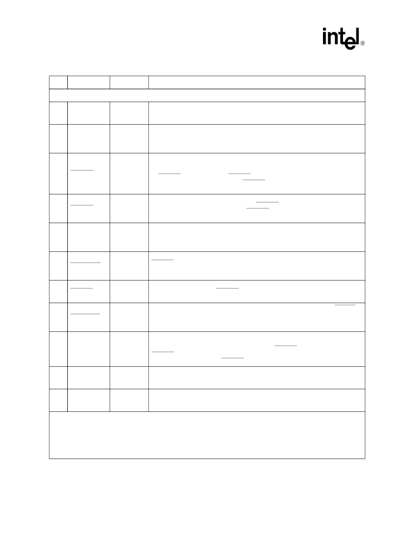
10 Mbps IRB Signals (Refer to Figure 23 on page 57)
9
IR10DAT
CMOS
I/O
OD, PD
10 Mbps IRB Data.
Carries data on the 10 Mbps IRB. Data is driven and sampled on
the rising edge of the corresponding IRCLK. This signal must be pulled up by a 330
resistor. Between boards, this signal can be buffered.
10
IR10CLK
Tri-state
Schmitt
CMOS I/O
PD
10 Mbps IRB Clock.
This bidirectional, non-continuous, 10 MHz clock is recovered
from received network traffic. During idle periods, the output is high-impedanced.
Schmitt triggering is used to increase noise immunity.
6
IR10DEN
TTL Output
OD
10 Mbps IRB Driver Enable.
This output provides directional control for an external
bidirectional transceiver (
‘
245) used to buffer the IRBs in multi-board applications. It
must be pulled up by a 330
resistor. When there are multiple devices on one board, tie
all
IR10DEN
outputs together. If
IR10DEN
is tied directly to the DIR pin on a
‘
245, attach
the on-board IR10DAT, IR10CLK and
IR10ENA
signals to the
“
B
”
side of the
‘
245, and
connect the off-board signals to the
“
A
”
side of the
‘
245.
8
IR10ENA
CMOS I/O
OD, PU
10 Mbps IRB Enable.
This active Low output indicates carrier presence on the IRB. A
330
pull-up resistor is required to pull the IR10ENA output High when the IRB is idle.
When there are multiple devices, tie all IR10ENA outputs together. This signal may be
buffered between boards.
3
IR10COL
CMOS I/O
OD, PU
10 Mbps IRB Collision.
This output is driven Low to indicate that a collision has
occurred on the 10 Mbps segment. A 330
resistor is required in each box to pull this
signal High when there is no collision. This signal should not be connected between
boards and it may not be buffered.
4
IR10COLBP
CMOS I/O
OD, NC
10 Mbps IRB Collision - Backplane.
This active Low output has the same function as
IR10COL
, but is used between boards. Attach this signal only from the device with
ChipID = 0 to the backplane or connector,
without buffering
. The output must be
pulled up by one 330
resistor per system.
1
IR10CFS
Analog I/O
OD
10 Mbps IRB Collision Force Sense.
This three-state analog signal indicates transmit
collision when driven Low. IR10CFS requires a 680
, 1% pull-up resistor. Do not
connect this signal between boards and do not buffer.
5
IR10CFSBP
Analog I/O
OD, NC
10 Mbps IRB Collision Force Sense - Backplane.
Functions the same as
IR10CFS
,
but connects between boards. Attach this signal only from the device with ChipID = 0 to
the backplane or connector,
without buffering
. This signal requires one 330
, 1% pull-
up resistor per system.
79
MACACTIVE
TTL Input
PD
MAC Active.
A TTL-level signal. Active High input allows external ASICs to participate
in 10 Mbps IRB. Driving data onto the IRB requires that the external ASIC assert
MACACTIVE High for one clock cycle, then assert IR10ENA Low. ASIC monitors
IR10COL (active Low) for collision. By using MACACTIVE, the repeater
—
not the
MAC
—
drives the three-level IR10CFS pin.
55
IR10 ISO
TTL Output
10 Mbps IRB Isolate.
By using IR10 IS, one LXT980 per board can enable or disable
an external bidirectional transceiver (
‘
245). Attach the output to the Enable input of the
‘
245. Driven High (disable) to isolate the 10 Mbps IRB.
80
HOLDCOL
TTL I/O
PD
Hold Collision for 10 Mbps mode.
This active High signal is driven by the device with
ChipID = 0 to extend a non-local transmit collision to other devices on the same board.
The HOLDCOL signals from different boards should NOT be attached together.
Table 4. Inter-Repeater Backplane Signal Descriptions (Continued)
Pin
Symbol
Type
1
Description
1. NC = No Clamp. Pad will not clamp input in the absence of power.
PU = Input contains pull-up.
PD = Input contains pull-down.
I/O = Input / Output.
OD = Open Drain
TTL = Transistor-Transistor Logic
Even if the IRB is not used, required pull-up resistors must be installed as listed above.
相關(guān)PDF資料 |
PDF描述 |
|---|---|
| LXT9880AHC | Controller Miscellaneous - Datasheet Reference |
| LXT9880HC | Controller Miscellaneous - Datasheet Reference |
| LXT9883HC | LAN HUB CONTROLLER |
| LZ1030M | Common Anode Diode Array |
| LZ1032AD | Interface IC |
相關(guān)代理商/技術(shù)參數(shù) |
參數(shù)描述 |
|---|---|
| LXT9880AHC | 制造商:未知廠家 制造商全稱:未知廠家 功能描述:Controller Miscellaneous - Datasheet Reference |
| LXT9880HC | 制造商:未知廠家 制造商全稱:未知廠家 功能描述:Controller Miscellaneous - Datasheet Reference |
| LXT9883 | 制造商:INTEL 制造商全稱:Intel Corporation 功能描述:Advanced 10/100 Umnmanaged Repeater |
| LXT9883HC | 制造商:未知廠家 制造商全稱:未知廠家 功能描述:LAN HUB CONTROLLER |
| LXTON/H0 | 制造商:Red Lion Controls 功能描述:ANNUN LABELS, 1 LPAX LABEL: TON/H 制造商:Red Lion Controls 功能描述:1 LPAX LABEL TON/H |
發(fā)布緊急采購,3分鐘左右您將得到回復(fù)。