- 您現(xiàn)在的位置:買賣IC網(wǎng) > PDF目錄369885 > LXT331PH LINE INTERFACE|CMOS|LDCC|44PIN|PLASTIC PDF資料下載
參數(shù)資料
| 型號(hào): | LXT331PH |
| 英文描述: | LINE INTERFACE|CMOS|LDCC|44PIN|PLASTIC |
| 中文描述: | 線路接口|的CMOS | LDCC | 44PIN |塑料 |
| 文件頁(yè)數(shù): | 18/32頁(yè) |
| 文件大小: | 395K |
| 代理商: | LXT331PH |
第1頁(yè)第2頁(yè)第3頁(yè)第4頁(yè)第5頁(yè)第6頁(yè)第7頁(yè)第8頁(yè)第9頁(yè)第10頁(yè)第11頁(yè)第12頁(yè)第13頁(yè)第14頁(yè)第15頁(yè)第16頁(yè)第17頁(yè)當(dāng)前第18頁(yè)第19頁(yè)第20頁(yè)第21頁(yè)第22頁(yè)第23頁(yè)第24頁(yè)第25頁(yè)第26頁(yè)第27頁(yè)第28頁(yè)第29頁(yè)第30頁(yè)第31頁(yè)第32頁(yè)

LXT331
—
Dual T1/E1 Line Interface Unit
18
Datasheet
2.4
Diagnostic Mode Operation
The LXT331 offers two diagnostic modes. Analog Loopback (ALOOP) and Transmit All Ones
(TAOS) are available under both Host and Hardware control modes.
In Host mode, diagnostic modes are selected by writing the appropriate SIO bits. In Hardware
mode, diagnostic modes are selected by a combination of pin settings. The pins must be held at the
specified levels for a minimum of 20 ns (typically).
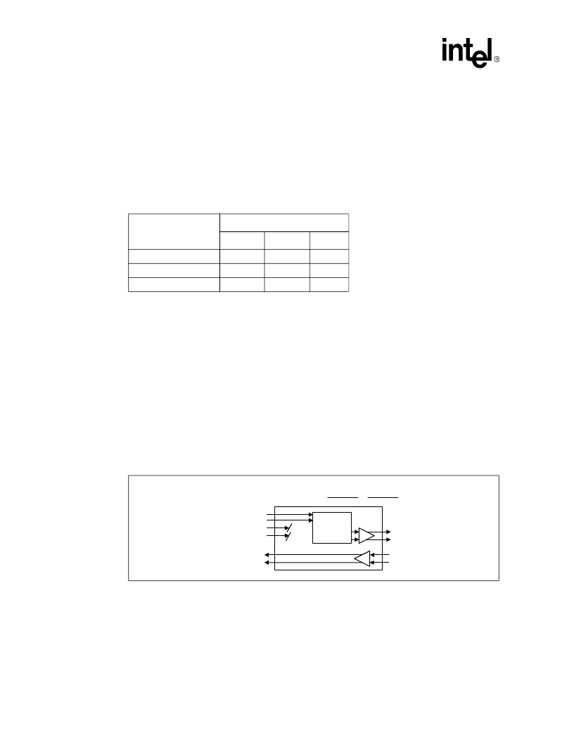
Table 5
lists Hardware Mode control settings
for the various diagnostic modes.
Transmit All Ones.
See
Figure 8
. Transmit All Ones
(TAOS) is selected when TAOS = 1. In
TAOS mode the TPOS and TNEG inputs are ignored, but the transmitter remains locked to the
TCLK input. When TAOS is selected, the transceiver transmits a continuous stream of 1s at the
TCLK frequency. If TCLK is not supplied, MCLK is used as the transmit reference. TAOS and
Analog Loopback can be selected simultaneously as shown in
Figure 9
.
Analog Loopback.
See
Figure 10
. Analog Loopback (ALOOP) is selected when ALOOP = 1. In
ALOOP mode the receive line input (RTIP/RRING) is blocked. The transmit outputs (TTIP and
TRING) are looped back through the receiver input and output at PMRK and NMRK. The
transmitter circuits are unaffected by ALOOP. Transmitting onto an improperly terminated line
may produce unexpected pulse widths at PMRK and NMRK.
Reset / Tri-State
. By holding the TRSTE pin High for at least 200 ns, all output drivers (both
digital and analog) go to the high Z state and the chip logic is reset. The reset/high Z state is
maintained for 6
μ
s after TRSTE returns Low.
Table 5. Hardware Mode Diagnostic Selection
Mode
LXT331 Pin
TRSTE
ALOOP
TAOS
Analog Loopback
L
H
L
Transmit All Ones
L
X
H
Reset/High Z
H
X
X
Figure 8. Transmit All Ones Data Path
CTTIP
Timing &
TAOS
TCLK
TPOS
TNEG
TTIP
TRING
RTIP
RRING
Transmit All Ones =
ALOOP
0
TAOS
1
PMRK
NMRK
相關(guān)PDF資料 |
PDF描述 |
|---|---|
| LXT331QE | LINE INTERFACE|CMOS|QFP|44PIN|PLASTIC |
| LXT331QH | LINE INTERFACE|CMOS|QFP|44PIN|PLASTIC |
| LXT332PE | Line Interface |
| LXT332QE | Line Interface |
| LXT334&LXT304A | LXT334 & LXT304A - LXT334 & LXT304A ?Low Cost & High Performance Quad E1 Interface Solution |
相關(guān)代理商/技術(shù)參數(shù) |
參數(shù)描述 |
|---|---|
| LXT331QE | 制造商:未知廠家 制造商全稱:未知廠家 功能描述:LINE INTERFACE|CMOS|QFP|44PIN|PLASTIC |
| LXT331QH | 制造商:未知廠家 制造商全稱:未知廠家 功能描述:LINE INTERFACE|CMOS|QFP|44PIN|PLASTIC |
| LXT332 | 制造商:LVL1 制造商全稱:LVL1 功能描述:Dual T1/E1 Line Interface Unit with Crystal-less Attenuation |
| LXT332PE | 制造商:未知廠家 制造商全稱:未知廠家 功能描述:Line Interface |
| LXT332QE | 制造商:未知廠家 制造商全稱:未知廠家 功能描述:Line Interface |
發(fā)布緊急采購(gòu),3分鐘左右您將得到回復(fù)。