- 您現(xiàn)在的位置:買賣IC網 > PDF目錄378652 > LU82541ER (INTEL CORP) 82541ER Gigabit Ethernet Controller PDF資料下載
參數(shù)資料
| 型號: | LU82541ER |
| 廠商: | INTEL CORP |
| 元件分類: | 微控制器/微處理器 |
| 英文描述: | 82541ER Gigabit Ethernet Controller |
| 中文描述: | 1 CHANNEL(S), 1000M bps, LOCAL AREA NETWORK CONTROLLER, PBGA196 |
| 封裝: | 15 X 15 MM, 1 MM PITCH, LEAD FREE, PLASTIC, BGA-196 |
| 文件頁數(shù): | 16/48頁 |
| 文件大小: | 284K |
| 代理商: | LU82541ER |
第1頁第2頁第3頁第4頁第5頁第6頁第7頁第8頁第9頁第10頁第11頁第12頁第13頁第14頁第15頁當前第16頁第17頁第18頁第19頁第20頁第21頁第22頁第23頁第24頁第25頁第26頁第27頁第28頁第29頁第30頁第31頁第32頁第33頁第34頁第35頁第36頁第37頁第38頁第39頁第40頁第41頁第42頁第43頁第44頁第45頁第46頁第47頁第48頁
82541ER Gigabit Ethernet Controller
10
Datasheet
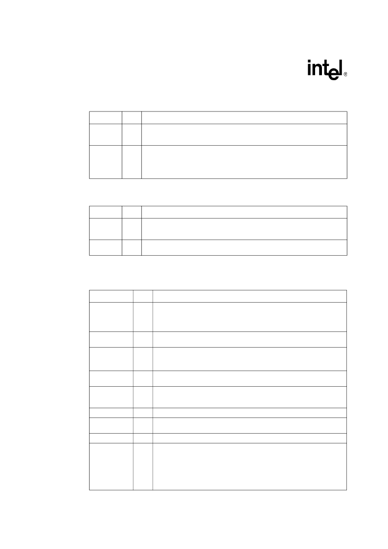
3.2.5
Error Reporting Signals (2)
3.2.6
Power Management Signals (2)
3.3
EEPROM and Serial FLASH Interface Signals (9)
Symbol
Type
Name and Function
SERR#
OD
System Error.
The System Error signal is used by the 82541ER controller to report
address parity errors. SERR# is open drain and is actively driven for a single PCI clock
when reporting the error.
PERR#
STS
Parity Error.
The Parity Error signal is used by the 82541ER controller to report data
parity errors during all PCI transactions except by a Special Cycle. PERR# is sustained
tri-state and must be driven active by the 82541ER controller two data clocks after a
data parity error is detected. The minimum duration of PERR# is one clock for each
data phase a data parity error is present.
Symbol
Type
Name and Function
LAN_PWR
GOOD
I
Power Good (Power-on Reset).
The Power Good signal is used to indicate that stable
power is available for the 82541ER. When the signal is low, the 82541ER holds itself in
reset state and floats all PCI signals.
AUX_PWR
I
Auxiliary Power.
If the Auxiliary Power signal is high, then auxiliary power is available
and the 82541ER device should support the D3cold power state.
Symbol
Type
Name and Function
EEMODE
I
EEPROM Mode.
The EEPROM Mode pin is used to select the interface and
source of the EEPROM used to initialize the device. For a MIcrowire* EEPROM on
the standard EEPROM pins, tie this pin to ground with a 100
pull-down resistor.
For a Serial Peripheral Interface (SPI*) EEPROM, leave this pin disconnected.
EEDI
O
EEPROM Data Input.
The EEPROM Data Input pin is used for output to the
memory device.
EEDO
I
EEPROM Data Output.
The EEPROM Data Output pin is used for input from the
memory device. The EEDO includes an internal pull-up resistor.
Note: Voltage for EEDO must be less than 0.7 V.
EECS
O
EEPROM Chip Select.
The EEPROM Chip Select signal is used to enable the
device.
EESK
O
EEPROM Serial Clock.
The EEPROM Shift Clock provides the clock rate for the
EEPROM interface, which is approximately 1 MHz for Microwire* and 2 MHZ for
SPI.
FLSH_CE#
O
Flash Chip Enable Output.
Used to enable FLASH device.
FLSH_SCK
O
Flash Serial Clock Output.
The clock rate of the serial FLASH interface is
approximately 1 MHz.
FLSH_SI
O
Flash Serial Data Input.
This pin is an output to the memory device.
FLSH_SO/
LAN_DISABLE#
I
Flash Serial Data Output / LAN Disable.
This pin is an input from the Flash
memory. Alternatively, the pin can be used to disable the LAN port from a system
General Purpose Input Output (GPIO) port. It has an internal pullup device. If the
82541ER is not using Flash functionality, the pin should be connected to an
external pull-up resistor.
If this pin is used as LAN_DISABLE#, the device goes to low power state and the
LAN port is disabled when this pin is sampled low on rising edge of PCI reset.
相關PDF資料 |
PDF描述 |
|---|---|
| LVT162245 | Low Voltage 16-Bit Transceiver with 3-STATE Outputs and 25? Series Resistors in A Port Outputs |
| LXT974 | Fast Ethernet 10/100 Quad Transceivers |
| LXT974A | Fast Ethernet 10/100 Quad Transceivers |
| LXT974AHC | Fast Ethernet 10/100 Quad Transceivers |
| LXT974B | Fast Ethernet 10/100 Quad Transceivers |
相關代理商/技術參數(shù) |
參數(shù)描述 |
|---|---|
| LU82541ER 862931 | 制造商:Intel 功能描述:TABOR; GIGABIT ETHERNET CONTROLLER, SINGLE PORT, PB-FREE 2LI - Trays |
| LU82541ER S L7QU | 制造商:Intel 功能描述:GIGABIT ETHERNET CONTROLLER 制造商:Intel 功能描述:TABOR; GIGABIT ETHERNET CONTROLLER, SINGLE PORT, PB-FREE 2LI - Tape and Reel |
| LU82541ER 862931 | 制造商:Intel 功能描述:Ethernet ICs Controller IEEE 10/ 100/1000 Mbps BGA196 |
| LU82541ER S L7QU | 制造商:Intel 功能描述:Ethernet ICs Controller IEEE 10/ 100/1000 Mbps BGA196 |
| LU82541GI | 制造商:INTEL 制造商全稱:Intel Corporation 功能描述:82541 Family of Gigabit Ethernet Controllers |
發(fā)布緊急采購,3分鐘左右您將得到回復。