- 您現(xiàn)在的位置:買賣IC網(wǎng) > PDF目錄361024 > LM2619MTC (NATIONAL SEMICONDUCTOR CORP) 500mA Step-Down DC-DC Converter PDF資料下載
參數(shù)資料
| 型號(hào): | LM2619MTC |
| 廠商: | NATIONAL SEMICONDUCTOR CORP |
| 元件分類: | 穩(wěn)壓器 |
| 英文描述: | 500mA Step-Down DC-DC Converter |
| 中文描述: | 1.1 A SWITCHING REGULATOR, 1000 kHz SWITCHING FREQ-MAX, PDSO14 |
| 封裝: | MO-153AB, TSSOP-14 |
| 文件頁(yè)數(shù): | 11/16頁(yè) |
| 文件大小: | 799K |
| 代理商: | LM2619MTC |
第1頁(yè)第2頁(yè)第3頁(yè)第4頁(yè)第5頁(yè)第6頁(yè)第7頁(yè)第8頁(yè)第9頁(yè)第10頁(yè)當(dāng)前第11頁(yè)第12頁(yè)第13頁(yè)第14頁(yè)第15頁(yè)第16頁(yè)
Device Information
(Continued)
PFM OPERATION
Connecting
LM2619MTC to hysteretic PFM operation. While in PFM
(Pulse Frequency Modulation) mode, the output voltage is
regulated by switching with a discrete energy per cycle and
then modulating the cycle rate, or frequency, to control
power to the load. This is done by using an error comparator
to sense the output voltage. The device waits as the load
discharges the output filter capacitor, until the output voltage
drops below the lower threshold of the PFM error-
comparator. Then the device initiates a cycle by turning on
the PFET switch. This allows current to flow from the input,
through the inductor to the output, charging the output filter
capacitor. The PFET is turned off when the output voltage
the
SYNC/MODE
to
SGND
sets
the
rises above the regulation threshold of the PFM error com-
parator. Thus, the output voltage ripple in PFM mode is
proportional to the hysteresis of the error comparator.
In PFM mode, the device only switches as needed to service
the load. This lowers current consumption by reducing power
consumed during the switching action in the circuit, due to
transition losses in the internal MOSFETs, gate drive cur-
rents, eddy current losses in the inductor, etc. It also im-
proves light-load voltage regulation. During the second half
of the cycle, the intrinsic body diode of the NFET synchro-
nous rectifier conducts until the inductor current ramps to
zero.
OPERATING MODE SELECTION
The LM2619MTC is designed for digital control of the oper-
ating modes by the system controller. This prevents the
spurious switch over from low-noise PWM mode between
transmission intervals in mobile phone applications that can
occur in other products.
The SYNC/MODE digital input pin is used to select the
operating mode. Setting SYNC/MODE high (above 1.3V)
selects 600kHz current-mode PWM operation. PWM mode
is optimized for low-noise, high-power operation for use
when the load is active. Setting SYNC/MODE low (below
0.4V) selects hysteretic voltage-mode PFM operation. PFM
mode is optimized for reducing power consumption and
extending battery life when the load is in a low-power
standby mode. In PFM mode, quiescent current into the V
pin is 160μA typ. In contrast, PWM mode V
DD
-pin quiescent
current is 600μA typ.
PWM operation is intended for use with loads of 50mA or
more, when low noise operation is desired. Below 100mA,
PFM operation can be used to allow precise regulation, and
reduced current consumption. The LM2619MTC has an
over-voltage feature that prevents the output voltage from
rising too high, when the device is left in PWM mode under
low-load conditions. See
Overvoltage Protection
, for more
information.
Switch modes with the SYNC/MODE pin, using a signal with
a slew rate faster than 5V/100μs. Use a comparator, Schmitt
trigger or logic gate to drive the SYNC/MODE pin. Do not
leave the pin floating or allow it to linger between thresholds.
These measures will prevent output voltage errors in re-
sponse to an indeterminate logic state. The LM2619MTC
switches on each rising edge of SYNC. Ensure a minimum
load to keep the output voltage in regulation when switching
modes frequently.
FREQUENCY SYNCHRONIZATION
The SYNC/MODE input can also be used for frequency
synchronization. During synchronization, the LM2619MTC
initiates cycles on the rising edge of the clock. When syn-
chronized to an external clock, it operates in PWM mode.
The device can synchronize to a 50% duty-cycle clock over
frequencies from 500kHz to 1MHz. If a different duty cycle is
used other than 50% the range for acceptable duty cycles is
30% to 70%.
Use the following waveform and duty cycle guidelines when
applying an external clock to the SYNC/MODE pin. Clock
under/overshoot should be less than 100mV below GND or
above V
. When applying noisy clock signals, especially
sharp edged signals from a long cable during evaluation,
terminate the cable at its characteristic impedance and add
an RC filter to the SYNC pin, if necessary, to soften the slew
rate and over/undershoot. Note that sharp edged signals
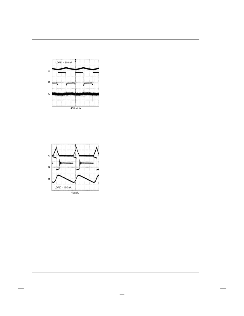
PWM Mode Switching Waveform
20065125
A: Inductor Current, 500mA/div
B: SW Pin, 2V/div
C: V
OUT
, 10mV/div, AC Coupled
FIGURE 6.
PFM Mode Switching Waveform
20065126
A: Inductor Current, 500mA/div
B: SW Pin, 2V/div
C: V
OUT
, 50mV/div, AC Coupled
FIGURE 7.
L
www.national.com
11
PrintDate=2003/08/20 PrintTime=18:54:05 801627bc ds200651_p Rev. No. 1.25
cmserv
Proof
Seq=11
相關(guān)PDF資料 |
PDF描述 |
|---|---|
| LM2619MTCX | 500mA Step-Down DC-DC Converter |
| LM2621MM | Low Input Voltage, Step-Up DC-DC Converter |
| LM2621 | |
| LM2622 | |
| LM2623 | |
相關(guān)代理商/技術(shù)參數(shù) |
參數(shù)描述 |
|---|---|
| LM2619MTC/NOPB | 功能描述:IC REG BUCK SYNC ADJ 14-TSSOP RoHS:是 類別:集成電路 (IC) >> PMIC - 穩(wěn)壓器 - DC DC 開(kāi)關(guān)穩(wěn)壓器 系列:- 產(chǎn)品培訓(xùn)模塊:Lead (SnPb) Finish for COTS Obsolescence Mitigation Program 標(biāo)準(zhǔn)包裝:1 系列:- 類型:降壓(降壓) 輸出類型:固定 輸出數(shù):1 輸出電壓:3.3V 輸入電壓:4.5 V ~ 24 V PWM 型:- 頻率 - 開(kāi)關(guān):- 電流 - 輸出:125mA 同步整流器:無(wú) 工作溫度:-40°C ~ 85°C 安裝類型:表面貼裝 封裝/外殼:SOT-23-6 包裝:Digi-Reel® 供應(yīng)商設(shè)備封裝:SOT-6 其它名稱:MAX1836EUT33#TG16DKR |
| LM2619MTCX | 制造商:NSC 制造商全稱:National Semiconductor 功能描述:500mA Step-Down DC-DC Converter |
| LM261J | 制造商:未知廠家 制造商全稱:未知廠家 功能描述:Analog Comparator |
| LM2621 | 制造商:NSC 制造商全稱:National Semiconductor 功能描述:Low Input Voltage, Step-Up DC-DC Converter |
| LM2621_05 | 制造商:NSC 制造商全稱:National Semiconductor 功能描述:Low Input Voltage, Step-Up DC-DC Converter |
發(fā)布緊急采購(gòu),3分鐘左右您將得到回復(fù)。