- 您現(xiàn)在的位置:買賣IC網(wǎng) > PDF目錄358810 > LM1269NA (NATIONAL SEMICONDUCTOR CORP) 110 MHz I2C Compatible RGB Video Amplifier System with OSD & DACs PDF資料下載
參數(shù)資料
| 型號: | LM1269NA |
| 廠商: | NATIONAL SEMICONDUCTOR CORP |
| 元件分類: | 音頻/視頻放大 |
| 英文描述: | 110 MHz I2C Compatible RGB Video Amplifier System with OSD & DACs |
| 中文描述: | 3 CHANNEL, VIDEO PREAMPLIFIER, PDIP24 |
| 封裝: | PLASTIC, DIP-24 |
| 文件頁數(shù): | 12/20頁 |
| 文件大?。?/td> | 1676K |
| 代理商: | LM1269NA |
Functional Description
(Continued)
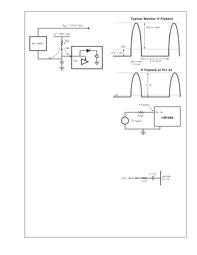
H Flyback:
H Flyback is an analog signal input from the
monitor horizontal scan. The “H Blank” section uses this
signal to add horizontal blanking to the output video signal.
This enables the user to blank at the cathodes during hori-
zontal flyback. An optional capacitor and/or resistor to
ground may be needed if noise interferes with the H Flyback
signal.
This feature gives very accurate timing for the horizontal
blanking; however, the flyback signal must be very clean.
There should be no ringing or other noise on the flyback
signal.
R
is used to limit the input current into the IC to a typical
value of + 1 mA during flyback and 100 μA during normal
forward scan. For example if an H flyback with a peak of
100V is used, R
= 100 k
. The internal input impedance
of pin 24 is low to limit the maximum voltage swing at the
input to within the supply rail and ground. The IC interface
circuit creates a digital signal from this waveform, which is
used as the blanking signal at the “Output Buffer Amp”. This
signal adds blanking to the video output signal. Figure 5
shows the H flyback waveforms and the location of R
LIMIT
. A
56 pF capacitor has been added to the H Flyback pin on the
demo board for filtering noise on the H Flyback signal.
H Blank:
Some customers may still prefer to use a standard
logic signal for the horizontal blanking. Pin 24 can be
adapted to accept a logic input. It is necessary for the current
flow into pin 24 to reverse for proper operation. Therefore the
logic signal must be AC coupled into pin 24. Figure 6 shows
the recommended circuit for a logic signal input. The blank
signal must be a positive pulse.
Power Save Mode:
There are two modes of power save:
1.
Blanking the video
2.
Turning off most of the power for maximum power sav-
ings.
In the first mode the video is completely blanked. By setting
bit-0 in register 9 to a 1 the video will be completely blanked.
This gives some power savings since there is no beam
current in the monitor. Maximum power saving is obtained in
the second mode. Bits 0 and 1 in register 9 should be set to
a 1. Bit 1 in register 9 turns off the video output stage of the
DS200099-26
FIGURE 4. ABL
DS200099-27
FIGURE 5. H Flyback Input Pulse
DS200099-28
FIGURE 6. Standard Logic H Blank
L
www.national.com
12
相關PDF資料 |
PDF描述 |
|---|---|
| LM1269 | 110 MHz I2C Compatible RGB Video Amplifier System with OSD & DACs |
| LM12S02 | Color STN LCD Module |
| LM12S402 | Color STN-LCD Module |
| LM12S44 | Color STN-LCD Module |
| LM12S47 | Color STN-LCD Module |
相關代理商/技術參數(shù) |
參數(shù)描述 |
|---|---|
| LM1269NA/NOPB | 功能描述:視頻放大器 RoHS:否 制造商:ON Semiconductor 通道數(shù)量:4 電源類型: 工作電源電壓:3.3 V, 5 V 電源電流: 最小工作溫度: 最大工作溫度: 封裝 / 箱體:TSSOP-14 封裝:Reel |
| LM1269NA/NOPB | 制造商:Texas Instruments 功能描述:Audio Power Amplifier IC |
| LM126H | 制造商:NSC 制造商全稱:National Semiconductor 功能描述:VOLTAGE REGULATORS |
| LM126H/883B | 制造商:Texas Instruments 功能描述:IC,VOLT REGULATOR,FIXED,+-12V,BIPOLAR,CAN,10PIN,METAL |
| LM126H/883C | 制造商:Texas Instruments 功能描述: |
發(fā)布緊急采購,3分鐘左右您將得到回復。