- 您現(xiàn)在的位置:買(mǎi)賣(mài)IC網(wǎng) > PDF目錄30714 > LA17000M AM/FM, AUDIO SINGLE CHIP RECEIVER, PQFP80 PDF資料下載
參數(shù)資料
| 型號(hào): | LA17000M |
| 元件分類(lèi): | 接收器 |
| 英文描述: | AM/FM, AUDIO SINGLE CHIP RECEIVER, PQFP80 |
| 封裝: | 14 X 14 MM, QFP-80 |
| 文件頁(yè)數(shù): | 15/54頁(yè) |
| 文件大?。?/td> | 830K |
| 代理商: | LA17000M |
第1頁(yè)第2頁(yè)第3頁(yè)第4頁(yè)第5頁(yè)第6頁(yè)第7頁(yè)第8頁(yè)第9頁(yè)第10頁(yè)第11頁(yè)第12頁(yè)第13頁(yè)第14頁(yè)當(dāng)前第15頁(yè)第16頁(yè)第17頁(yè)第18頁(yè)第19頁(yè)第20頁(yè)第21頁(yè)第22頁(yè)第23頁(yè)第24頁(yè)第25頁(yè)第26頁(yè)第27頁(yè)第28頁(yè)第29頁(yè)第30頁(yè)第31頁(yè)第32頁(yè)第33頁(yè)第34頁(yè)第35頁(yè)第36頁(yè)第37頁(yè)第38頁(yè)第39頁(yè)第40頁(yè)第41頁(yè)第42頁(yè)第43頁(yè)第44頁(yè)第45頁(yè)第46頁(yè)第47頁(yè)第48頁(yè)第49頁(yè)第50頁(yè)第51頁(yè)第52頁(yè)第53頁(yè)第54頁(yè)

LA17000M
No. 6522-22/54
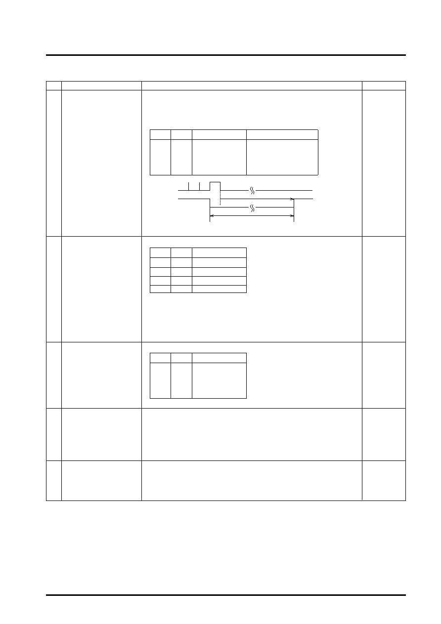
Continued from preceding page.
No.
Control block/Data
Description
Related data
Unlock detection data
This data selects the phase error (E) detection width that is used for evaluating
PLL lock.
If a phase error that exceeds the E detection width in the following table is
generated, the signal is deemed to be unlocked. When the signal is unlocked,
the detection pin (DO or I/O-5) goes low.
UL1, UL0
This is the crystal oscillator selection data.
* When a power-on reset is executed, 10.25 MHz is selected.
Crystal oscillator buffer (XBUF) output control data.
XB = 0: Buffer output: OFF (This mode is selected when a power-on reset is
executed.)
XB = 1: Buffer output ON
* For FM reception (using the PD0 pin), XBUF output must be off.
This data controls the phase comparator dead zone.
When a power-on reset is executed, DZA is selected.
This data is used to force the charge pump output to the low level (VSS level).
DLC = 1: Low level
= 0: Normal operation
* If a deadlock occurs because the VCO control voltage (Vtune) is 0 V and VCO
oscillation is stopped, it is possible to escape the deadlock by forcing the
charge pump output to low level and setting Vtune to VCC.
When a power-on reset is executed, normal operation mode is selected.
This is the IC test data.
Set TEST0 = 0.
TEST1 = 0
TEST2 = 0
* When a power-on reset is executed, all the test data is set to zero.
(12)
ULD
DT0, DT1
R0 to R3
(13)
UL1
DT0
E detection width
Detection pin output
0
Stop
Open
0
1
0
Direct output of E
1
0
±0.5
s
Extend E by 1 to 2 ms
11
±1
s
Extend E by 1 to 2 ms
Unlocked output
XS1
XS0
X’tal OSC
0
Prohibited
0
1
Prohibited
1
0
10.25 MHz
1
10.35 MHz
DZ1
DZ0
Dead zone mode
0
DZA
0
1
DZB
1
0
DZC
1
DZD
(14)
(15)
(16)
Extention
Crystal oscillator circuit
XS0, XS1
XB
Phase comparator control
data
DZ0, DZ1
Charge pump control data
DLC
IC test data
TEST0
TEST1
TEST2
相關(guān)PDF資料 |
PDF描述 |
|---|---|
| LA1776M | 2-BAND, AUDIO TUNER, PQFP64 |
| LA1776M | 2-BAND, AUDIO TUNER, PQFP64 |
| LA1780M | 2-BAND, AUDIO TUNER, PQFP64 |
| LA1781M | AM/FM, AUDIO SINGLE CHIP RECEIVER, PQFP64 |
| LA1784M | AM/FM, AUDIO SINGLE CHIP RECEIVER, PQFP64 |
相關(guān)代理商/技術(shù)參數(shù) |
參數(shù)描述 |
|---|---|
| LA17000ML-MPB-E | 制造商:Sony Semiconductor Solutions Division 功能描述: |
| LA171B-3G-PF | 制造商:LIGITEK 制造商全稱(chēng):LIGITEK electronics co., ltd. 功能描述:LED ARRAY |
| LA171B-GGH-PF | 制造商:LIGITEK 制造商全稱(chēng):LIGITEK electronics co., ltd. 功能描述:LED ARRAY |
| LA171B-YGG-PF | 制造商:LIGITEK 制造商全稱(chēng):LIGITEK electronics co., ltd. 功能描述:LED ARRAY |
| LA174B-2G-PF | 制造商:LIGITEK 制造商全稱(chēng):LIGITEK electronics co., ltd. 功能描述:LED ARRAY |
發(fā)布緊急采購(gòu),3分鐘左右您將得到回復(fù)。