- 您現(xiàn)在的位置:買(mǎi)賣IC網(wǎng) > PDF目錄377599 > L800BB90VK (Advanced Micro Devices, Inc.) 8 Megabit (1 M x 8-Bit/512 K x 16-Bit) CMOS 3.0 Volt-only Boot Sector Flash Memory PDF資料下載
參數(shù)資料
| 型號(hào): | L800BB90VK |
| 廠商: | Advanced Micro Devices, Inc. |
| 英文描述: | 8 Megabit (1 M x 8-Bit/512 K x 16-Bit) CMOS 3.0 Volt-only Boot Sector Flash Memory |
| 中文描述: | 8兆位(1 M中的x 8-Bit/512畝x 16位),3.0伏的CMOS只引導(dǎo)扇區(qū)閃存 |
| 文件頁(yè)數(shù): | 16/49頁(yè) |
| 文件大小: | 859K |
| 代理商: | L800BB90VK |
第1頁(yè)第2頁(yè)第3頁(yè)第4頁(yè)第5頁(yè)第6頁(yè)第7頁(yè)第8頁(yè)第9頁(yè)第10頁(yè)第11頁(yè)第12頁(yè)第13頁(yè)第14頁(yè)第15頁(yè)當(dāng)前第16頁(yè)第17頁(yè)第18頁(yè)第19頁(yè)第20頁(yè)第21頁(yè)第22頁(yè)第23頁(yè)第24頁(yè)第25頁(yè)第26頁(yè)第27頁(yè)第28頁(yè)第29頁(yè)第30頁(yè)第31頁(yè)第32頁(yè)第33頁(yè)第34頁(yè)第35頁(yè)第36頁(yè)第37頁(yè)第38頁(yè)第39頁(yè)第40頁(yè)第41頁(yè)第42頁(yè)第43頁(yè)第44頁(yè)第45頁(yè)第46頁(yè)第47頁(yè)第48頁(yè)第49頁(yè)
14
Am29LV800B
Autoselect Mode
The autoselect mode provides manufacturer and
device identification, and sector protection verifica-
tion, through identifier codes output on DQ7–DQ0.
This mode is primarily intended for programming
equipment to automatically match a device to be pro-
grammed with its corresponding programming algo-
rithm. However, the autoselect codes can also be
accessed in-system through the command register.
When using programming equipment, the autoselect
mode requires V
ID
(11.5 V to 12.5 V) on address pin
A9. Address pins A6, A1, and A0 must be as shown in
Table 4. In addition, when verifying sector protection,
the sector address must appear on the appropriate
highest order address bits (see Tables 2 and 3). Table
4 shows the remaining address bits that are don’t
care. When all necessary bits have been set as
required, the programming equipment may then read
the corresponding identifier code on DQ7–DQ0.
To access the autoselect codes in-system, the host
system can issue the autoselect command via the
command register, as shown in Table 1. This method
does not require V
ID
. See “Command Definitions” for
details on using the autoselect mode.
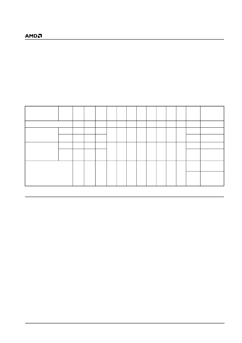
Table 4. Am29LV800B Autoselect Codes ( High Voltage Method)
L = Logic Low = V
IL
, H = Logic High = V
IH
, SA = Sector
Address, X = Don’t care.
Sector Protection/Unprotection
The hardware sector protection feature disables both
program and erase operations in any sector. The
hardware sector unprotection feature re-enables both
program and erase operations in previously protected
sectors.
The device is shipped with all sectors unprotected.
AMD offers the option of programming and protecting
sectors at its factory prior to shipping the device
through AMD’s ExpressFlash Service. Contact an
AMD representative for details.
It is possible to determine whether a sector is pro-
tected or unprotected. See “Autoselect Mode” for
details.
Sector Protection/unprotection can be implemented
via two methods.
The primary method requires V
ID
on the RESET# pin
only, and can be implemented either in-system or via
programming equipment. Figure 2 shows the algo-
rithms and Figure 23 shows the timing diagram. This
method uses standard microprocessor bus cycle
timing. For sector unprotect, all unprotected sectors
must first be protected prior to the first sector unpro-
tect write cycle.
The alternate method intended only for programming
equipment requires V
ID
on address pin A9 and OE#.
This method is compatible with programmer routines
written for earlier 3.0 volt-only AMD flash devices.
Publication number 20536 contains further details;
contact an AMD representative to request a copy.
Temporary Sector Unprotect
This feature allows temporary unprotection of previ-
ously protected sectors to change data in-system.
The Sector Unprotect mode is activated by setting the
RESET# pin to V
ID
. During this mode, formerly pro-
tected sectors can be programmed or erased by
selecting the sector addresses. Once V
ID
is removed
from the RESET# pin, all the previously protected
sectors are protected again. Figure 1 shows the algo-
rithm, and Figure 22 shows the timing diagrams, for
this feature.
Description
Mode
CE#
OE#
W E#
A18
to
A12
A11
to
A10
A9
A8
to
A7
A6
A5
to
A2
A1
A0
DQ8
to
DQ15
DQ7
to
DQ0
Manufacturer ID
:
AMD
L
L
H
X
X
V
ID
X
L
X
L
L
X
01h
Device ID:
Am29LV800B
(Top Boot Block)
Word
L
L
H
X
X
V
ID
X
L
X
L
H
22h
DAh
Byte
L
L
H
X
DAh
Device ID:
Am29LV800B
(Bottom Boot
Block)
Word
L
L
H
X
X
V
ID
X
L
X
L
H
22h
5Bh
Byte
L
L
H
X
5Bh
Sector Protection
Verification
L
L
H
SA
X
V
ID
X
L
X
H
L
X
01h
(protected)
X
00h
(unprotected
)
相關(guān)PDF資料 |
PDF描述 |
|---|---|
| L800BT12VC | 8 Megabit (1 M x 8-Bit/512 K x 16-Bit) CMOS 3.0 Volt-only Boot Sector Flash Memory |
| L800BT12VD | 8 Megabit (1 M x 8-Bit/512 K x 16-Bit) CMOS 3.0 Volt-only Boot Sector Flash Memory |
| L800BT12VE | 8 Megabit (1 M x 8-Bit/512 K x 16-Bit) CMOS 3.0 Volt-only Boot Sector Flash Memory |
| L800BT12VF | 8 Megabit (1 M x 8-Bit/512 K x 16-Bit) CMOS 3.0 Volt-only Boot Sector Flash Memory |
| L800BT12VI | 8 Megabit (1 M x 8-Bit/512 K x 16-Bit) CMOS 3.0 Volt-only Boot Sector Flash Memory |
相關(guān)代理商/技術(shù)參數(shù) |
參數(shù)描述 |
|---|---|
| L800BT12VC | 制造商:AMD 制造商全稱:Advanced Micro Devices 功能描述:8 Megabit (1 M x 8-Bit/512 K x 16-Bit) CMOS 3.0 Volt-only Boot Sector Flash Memory |
| L800BT12VD | 制造商:AMD 制造商全稱:Advanced Micro Devices 功能描述:8 Megabit (1 M x 8-Bit/512 K x 16-Bit) CMOS 3.0 Volt-only Boot Sector Flash Memory |
| L800BT12VE | 制造商:AMD 制造商全稱:Advanced Micro Devices 功能描述:8 Megabit (1 M x 8-Bit/512 K x 16-Bit) CMOS 3.0 Volt-only Boot Sector Flash Memory |
| L800BT12VF | 制造商:AMD 制造商全稱:Advanced Micro Devices 功能描述:8 Megabit (1 M x 8-Bit/512 K x 16-Bit) CMOS 3.0 Volt-only Boot Sector Flash Memory |
| L800BT12VI | 制造商:AMD 制造商全稱:Advanced Micro Devices 功能描述:8 Megabit (1 M x 8-Bit/512 K x 16-Bit) CMOS 3.0 Volt-only Boot Sector Flash Memory |
發(fā)布緊急采購(gòu),3分鐘左右您將得到回復(fù)。