- 您現(xiàn)在的位置:買賣IC網(wǎng) > PDF目錄383236 > L6238S (意法半導(dǎo)體) 12V Sensorless Spindle Motor Controller(主軸馬達(dá)控制器) PDF資料下載
參數(shù)資料
| 型號: | L6238S |
| 廠商: | 意法半導(dǎo)體 |
| 英文描述: | 12V Sensorless Spindle Motor Controller(主軸馬達(dá)控制器) |
| 中文描述: | 12V的傳感器主軸電機(jī)控制器(主軸馬達(dá)控制器) |
| 文件頁數(shù): | 23/31頁 |
| 文件大小: | 324K |
| 代理商: | L6238S |
第1頁第2頁第3頁第4頁第5頁第6頁第7頁第8頁第9頁第10頁第11頁第12頁第13頁第14頁第15頁第16頁第17頁第18頁第19頁第20頁第21頁第22頁當(dāng)前第23頁第24頁第25頁第26頁第27頁第28頁第29頁第30頁第31頁
C
off
to discharge to dischargtethrough R
slew
, initi-
ating the Constant-OFF time-out. When the volt-
age on C
off
reaches 1.2V, comparator A1switches
state toggling the latch in the opposite state, turn-
ing the upper driver back ON. SW1 also closed
quickly charging up C
off
for the nextcycle.
5.1 PWM Design Considerations
In order to select the parameters associated with
PWM operation, the following factors must be
takeninto consideration:
1. PWM Switching Frequency
2. Duty Cycle
3. Motor Currents
4. Minimum ON Time
5. Noise Blanking
6. Bemf Masking/Sampling
5.1.1. PWM Switching Frequency
The PWM switching frequency F
pwm
is found
from:
F
pwm
=
1
T
on
+
T
off
(5.1.1)
where:
T
on
= The time required for the motor current
to reach the commanded level.
T
off
= The programmedOFF time.
The two main considerations for this parameter
are the minimum and maximum switching fre-
quency.
The maximum switching frequency occurs during
the Start-up and should be kept below 50KHzdue
tointentional bandwidth limitations and output
switching losses.
5.1.2 Duty Cycle
Besides reducing the power dissipation of the
controller output stage, running in PWM offers 2
additional”free” benefits:
A. Reduced Powe SupplyCurrent at StartUp
B. Lower PowerRating for the Motor Current
SenseResistor.
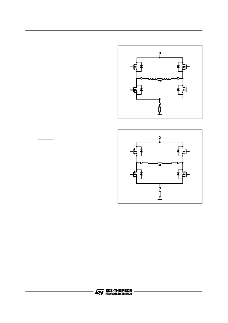
Figure 5-2 is the current path during the ON time
of a phase period. The current from the supply
passes through the upper sourcing DMOS, Q3
transistor through the two driven winding, the
lower DMOS, Q2 and finally through the current
sensing resistor R
sns
. Since both Q3 and Q4 are
ON, while Q3 is turnedOFF. The voltage,causing
the current to continue to flow through Q2, and
Q4.
If the duty cycle is nearor at 50%, then for 1/2 the
PWM cycle, no current is flowing from the power
supply or the sense resistor while current is still
flowing in the motor. This lowers the requirement
for both the Power Supply and the Power Rating
for the sensing resistor.
5.1.3 Motor Currents
Note:
It is not the objective of thissection to describe the principles
of brushless DCmotor, buttoprovide sufficient informationabout the
parameters associated with PWM operation in order to optimize an
application.
A simplifiedmodel of a motoris shown in figure 5-
4. For this discussion, lower order effects due to
mutual inductance between windings, resistance
due to losses in the magnetic circuit, etc. are not
shown.
The motor at
stall
is equal to a resistance,
Rmtr
,
in serieswith an inductance,
Lmtr
. When the mo-
tor is rotating, there is an induced emf that ap-
pears across the armaure terminals and is shown
in figure 5-4 as an internally generated voltage
Ibemf),
Eg
.
L1
L2
OUTPUTA
OUTPUTB
D2
D1
D4
D3
Q1
Q2
Q3
Q4
V
POWER
R
SENSE
R
SNS
D95IN319
Figure5-2
L1
L2
OUTPUTA
OUTPUTB
D2
D1
D4
D3
Q1
Q2
Q3
Q4
V
POWER
R
SENSE
R
SNS
D95IN320
Figure5-3
L6238S
23/31
相關(guān)PDF資料 |
PDF描述 |
|---|---|
| L6238 | Sensorless Spindle Motor Driver(無傳感器主軸電機(jī)驅(qū)動器) |
| L6239 | 12V Disk Drive Spindle Driver(12V磁盤驅(qū)動主軸驅(qū)動器) |
| L6242 | VOICE COIL MOTOR DRIVER |
| L6243 | VOICE COIL MOTOR DRIVER |
| L6243D | VOICE COIL MOTOR DRIVER |
相關(guān)代理商/技術(shù)參數(shù) |
參數(shù)描述 |
|---|---|
| L6238SQA | 制造商:STMICROELECTRONICS 制造商全稱:STMicroelectronics 功能描述:12V SENSORLESS SPINDLE MOTOR CONTROLLER |
| L6238SQT | 制造商:STMICROELECTRONICS 制造商全稱:STMicroelectronics 功能描述:12V SENSORLESS SPINDLE MOTOR CONTROLLER |
| L6239 | 制造商:未知廠家 制造商全稱:未知廠家 功能描述: |
| L623C | 制造商:未知廠家 制造商全稱:未知廠家 功能描述:THYRISTOR MODULE|BRIDGE|HALF-CNTLD|CA|280V V(RRM)|46A I(T) |
| L623F | 制造商:未知廠家 制造商全稱:未知廠家 功能描述:THYRISTOR MODULE|BRIDGE|HALF-CNTLD|CA|280V V(RRM)|46A I(T) |
發(fā)布緊急采購,3分鐘左右您將得到回復(fù)。