- 您現(xiàn)在的位置:買賣IC網(wǎng) > PDF目錄383236 > L6238S (意法半導(dǎo)體) 12V Sensorless Spindle Motor Controller(主軸馬達(dá)控制器) PDF資料下載
參數(shù)資料
| 型號(hào): | L6238S |
| 廠商: | 意法半導(dǎo)體 |
| 英文描述: | 12V Sensorless Spindle Motor Controller(主軸馬達(dá)控制器) |
| 中文描述: | 12V的傳感器主軸電機(jī)控制器(主軸馬達(dá)控制器) |
| 文件頁(yè)數(shù): | 22/31頁(yè) |
| 文件大?。?/td> | 324K |
| 代理商: | L6238S |
第1頁(yè)第2頁(yè)第3頁(yè)第4頁(yè)第5頁(yè)第6頁(yè)第7頁(yè)第8頁(yè)第9頁(yè)第10頁(yè)第11頁(yè)第12頁(yè)第13頁(yè)第14頁(yè)第15頁(yè)第16頁(yè)第17頁(yè)第18頁(yè)第19頁(yè)第20頁(yè)第21頁(yè)當(dāng)前第22頁(yè)第23頁(yè)第24頁(yè)第25頁(yè)第26頁(yè)第27頁(yè)第28頁(yè)第29頁(yè)第30頁(yè)第31頁(yè)
The high current flows from the grounded sub-
strate of the integrated circuit (p-type material),
throughone or more epitaxial pockets(n-type ma-
terial) and out the centerpar pin.
This current can cause adverse operation of the
controllet due to substrate injection and might
possibility damage the internal metalization runs.
The normal current for this input is in the 200
μ
A
range.
Referring to figure 4-13, a simple protection
scheme consisting of a 1K resistor and a low cur-
rent Schottky diode should be added if the appli-
cation causes excessive current (i.e. >1mA) to
flow through the center tap pin.
5.0 PWM MOTOR CURRENT CONTROL
A unique feature of the L6238S in the optional
Pulse Width Modulation (PWM) control of motor
current.
Using Variable-frequency, Constant-OFF time
Current-Mode control, the L6238S can drive
higher power motors without the need for external
drivers, while minimizing internal power dissipa-
tion.
Additional benefits include reduced power supply
consumption(up to 50% savings)and lower watt-
age requirements for the current sensingresistor.
Constant-OFF time Current-Mode control, oper-
ates on the principle of monitoring the motor cur-
rent and comparison it to a reference or control
level.
When the motorcurrent reachesthis commanded
level, the output drivers turn OFF and remain
OFFfor a Constant-OFF time. After this OFF time
the drivers turn back ON to repeat the cycle.
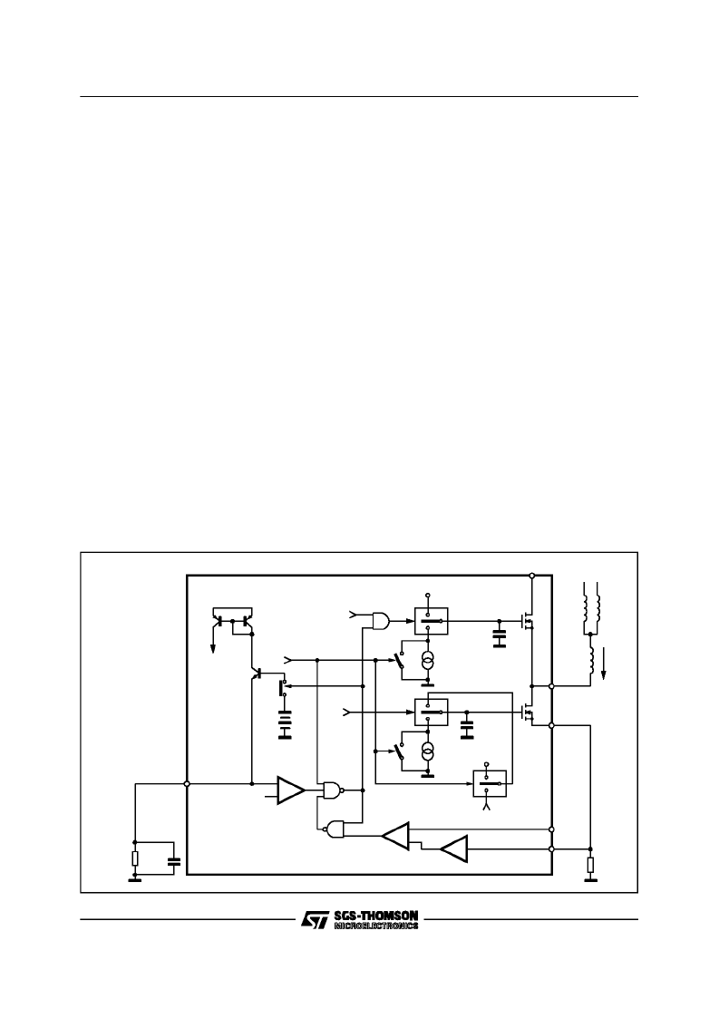
Figure 5.1 is a block diagram of the PWM control
circuitry. When using PWM as opposed to linear
control, two changes are made to the control
loop:
1.The slew rate control is disabled,allowing the
outputs to slew at a minimum rate of 10V/
μ
s.
This is accomplished by closing SW3 and
SW5.
2.The OTA amplifier is taken out of the control
loop via SW6. The lower drivers are now
driven into hard conductionby tying the gates
to the analogsupply during the On time of the
PWM cycle.
The currentin the motor windingsis monitored via
the voltage dropped in the sensing resistor,
R
sense
.
This voltage is multiplied by a factor of 4 in the
Current Sense Amplifier (CSA) and sent to nega-
tive inputof the PWMComparator (A2).
The control voltage, V
control
, is applied to the posi-
tive input of A2. When the output of the CSA
reaches a level that is equal to the commanded
level, the output of A2 switches low, toggling the
latch comprised of N1 and N2. This causes the
upper drivers to turn off andopens SW1. Q3 turns
OFF allowing the Constant-OFF time capacitors,
I1
Islew
V
PUMP
SW2
1
0
Cfet
UPPER A
+
-
A1
PWM/SLEW
X4
A3
VPOWER
I2
Islew
SW3
1
0
Cfet
OUTPUT
B
C
OUTA
L1
L2
L3
Q4
Q5
SLEW RATE
REFERENCE
CURRENT
R
SLW
RSENSE
CSA
VCTRL
LOWER A
D95IN318
N3
Q1
Q2
VANALOG
3.1V
SW1
Q3
1.2V
SW5
N1
SW4
N2
A2
+
-
PWM/LIN
CONTROL
1
0
FROM TRANS. LOOP
CSA
SW6
V
ANALOG
COFF
RSLEW
Figure 5-1
L6238S
22/31
相關(guān)PDF資料 |
PDF描述 |
|---|---|
| L6238 | Sensorless Spindle Motor Driver(無(wú)傳感器主軸電機(jī)驅(qū)動(dòng)器) |
| L6239 | 12V Disk Drive Spindle Driver(12V磁盤驅(qū)動(dòng)主軸驅(qū)動(dòng)器) |
| L6242 | VOICE COIL MOTOR DRIVER |
| L6243 | VOICE COIL MOTOR DRIVER |
| L6243D | VOICE COIL MOTOR DRIVER |
相關(guān)代理商/技術(shù)參數(shù) |
參數(shù)描述 |
|---|---|
| L6238SQA | 制造商:STMICROELECTRONICS 制造商全稱:STMicroelectronics 功能描述:12V SENSORLESS SPINDLE MOTOR CONTROLLER |
| L6238SQT | 制造商:STMICROELECTRONICS 制造商全稱:STMicroelectronics 功能描述:12V SENSORLESS SPINDLE MOTOR CONTROLLER |
| L6239 | 制造商:未知廠家 制造商全稱:未知廠家 功能描述: |
| L623C | 制造商:未知廠家 制造商全稱:未知廠家 功能描述:THYRISTOR MODULE|BRIDGE|HALF-CNTLD|CA|280V V(RRM)|46A I(T) |
| L623F | 制造商:未知廠家 制造商全稱:未知廠家 功能描述:THYRISTOR MODULE|BRIDGE|HALF-CNTLD|CA|280V V(RRM)|46A I(T) |
發(fā)布緊急采購(gòu),3分鐘左右您將得到回復(fù)。