- 您現(xiàn)在的位置:買賣IC網(wǎng) > PDF目錄383117 > IR3Y48 (Sharp Corporation) TUBING TEFLON .018 ID 100' CLR PDF資料下載
參數(shù)資料
| 型號(hào): | IR3Y48 |
| 廠商: | Sharp Corporation |
| 英文描述: | TUBING TEFLON .018 ID 100' CLR |
| 中文描述: | CCD信號(hào)處理 |
| 文件頁(yè)數(shù): | 23/31頁(yè) |
| 文件大小: | 176K |
| 代理商: | IR3Y48 |
第1頁(yè)第2頁(yè)第3頁(yè)第4頁(yè)第5頁(yè)第6頁(yè)第7頁(yè)第8頁(yè)第9頁(yè)第10頁(yè)第11頁(yè)第12頁(yè)第13頁(yè)第14頁(yè)第15頁(yè)第16頁(yè)第17頁(yè)第18頁(yè)第19頁(yè)第20頁(yè)第21頁(yè)第22頁(yè)當(dāng)前第23頁(yè)第24頁(yè)第25頁(yè)第26頁(yè)第27頁(yè)第28頁(yè)第29頁(yè)第30頁(yè)第31頁(yè)
NOTES :
1. Normally : Signal path through CDS
/
AGC
/
ADC
In this case analog input range is downward
from clamp voltage.
ADIN
: Signal bypassing CDS (Direct AGC or ADC
input)
In this case analog input range is upward
from clamp voltage.
2. Specified at MONOUT pin. The noise bandwidth is 100
kHz to 5 MHz.
3. Bandwidth from CCDIN/REFIN to ADC. The bandwidth
is specified as the settling time of ADC output for step
input (full scale – 1 dB) response (at gain = min.).
4. Black calibration period is the period of stabilization of
output code within ±1 LSB (average) compared to register
value for the black level code of 0 to 50% of the full scale
input. (Assuming external capacitance = 0.033 μF.)
External capacitor value to OBCAP pin determines the
bandwidth of the black level cancel loop. Since the gain
of the loop depends on sampling frequency, the
maximum frequency (settling within certain pixels) and
the minimum frequency (avoiding oscillation of the circuit)
are defined.
5. Select the external capacitor referring the following list
based on the minimum and maximum operating
frequencies.
If the black level settling specification (within 2 000
pixels) could be ignored, the maximum sampling
frequency for 0.1 μF and 0.33 μF will extend according
to the increment.
IR3Y48M
23
Analog Specifications
(Unless otherwise specified, AV
DD
= DV
DD
= 3.0 V, T
A
= +25 C, signal frequency f
IN
= 1 MHz,
signal level = –1 dB (full scale))
The current direction flowing into the pin is positive direction.
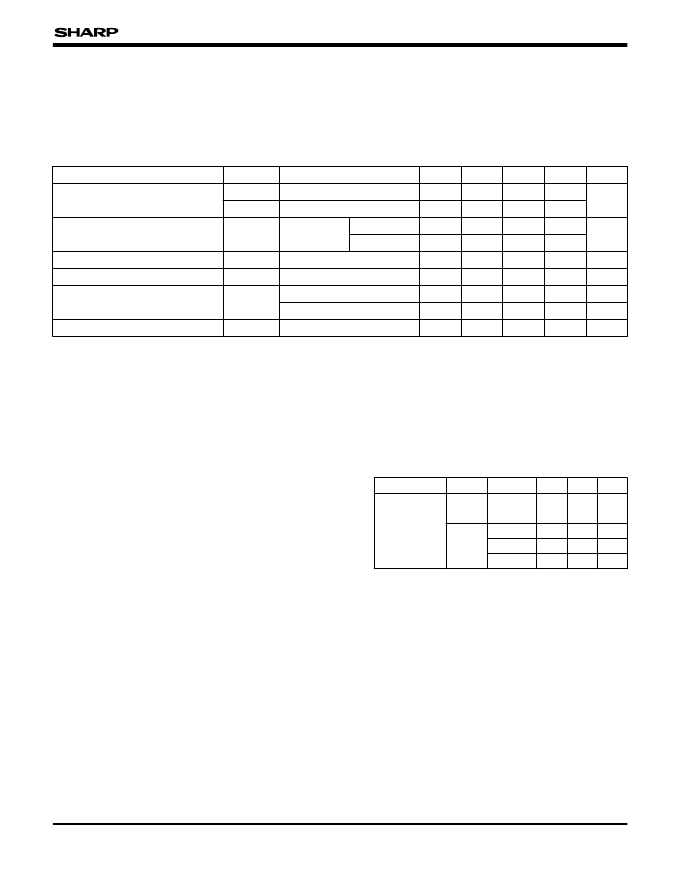
CDS & CLAMP CIRCUITS
PARAMETER
(Sampling frequency f
S
= 20 MHz)
TYP.
MIN.
MAX.
1.1
1.1
SYMBOL
V
ICDS
V
IAI
CONDITIONS
Normally
At ADIN
UNIT
Vp-p
Vp-p
NOTE
Analog input range
100
400
15
μV
rms
μV
rms
pF
pixel
V
V
pixel
1
At fs = 20 MHz
NI
Input referred noise
At gain = max.
At gain = min.
Input capacitance
Input Bandwidth
C
IN
CBW
CCDIN, ADIN & REFIN
1
3
2
Clamp voltage
1.95
1.45
1.8
1.3
1.65
1.15
Normally
At ADIN
V
CLPCAP
Black calibration period
4, 5
2000
t
BKCAL
PARAMETER
MODE
20 MHz
mode
OBCAP
MAX.
MIN.
Available
sampling
frequency
7.6
20
0.033 μF
MHz
UNIT
MHz
0.33 μF
1.7
0.6
MHz
0.1 μF
5.7
2.2
MHz
0.033 μF
15
5.8
15 MHz
mode
相關(guān)PDF資料 |
PDF描述 |
|---|---|
| IR3Y48A1 | CCD SIGNAL PROCESS & DIGITAL INTERFACE IC |
| IR3Y48M | CCD Signal Process & Digital Interface IC |
| IR42-21C | 1.8MM ROUND SUBMINIATURE INFRARED LED |
| IR9022 | Low Power Dual Operational Amplifier |
| IR9022N | Low Power Dual Operational Amplifier |
相關(guān)代理商/技術(shù)參數(shù) |
參數(shù)描述 |
|---|---|
| IR3Y48A1 | 制造商:SHARP 制造商全稱:Sharp Electrionic Components 功能描述:CCD SIGNAL PROCESS & DIGITAL INTERFACE IC |
| IR3Y48M | 制造商:SHARP 制造商全稱:Sharp Electrionic Components 功能描述:CCD Signal Process & Digital Interface IC |
| IR-4 | 制造商:VISHAY 制造商全稱:Vishay Siliconix 功能描述:Inductors Epoxy Conformal Coated Uniform Roll Coated |
| IR4 68UH | 制造商: 功能描述: 制造商:undefined 功能描述: |
發(fā)布緊急采購(gòu),3分鐘左右您將得到回復(fù)。