- 您現(xiàn)在的位置:買賣IC網(wǎng) > PDF目錄360914 > IQX320-15PP391I User Programmable Special Function ASIC PDF資料下載
參數(shù)資料
| 型號: | IQX320-15PP391I |
| 英文描述: | User Programmable Special Function ASIC |
| 中文描述: | 用戶可編程ASIC的特殊功能 |
| 文件頁數(shù): | 16/65頁 |
| 文件大小: | 620K |
| 代理商: | IQX320-15PP391I |
第1頁第2頁第3頁第4頁第5頁第6頁第7頁第8頁第9頁第10頁第11頁第12頁第13頁第14頁第15頁當前第16頁第17頁第18頁第19頁第20頁第21頁第22頁第23頁第24頁第25頁第26頁第27頁第28頁第29頁第30頁第31頁第32頁第33頁第34頁第35頁第36頁第37頁第38頁第39頁第40頁第41頁第42頁第43頁第44頁第45頁第46頁第47頁第48頁第49頁第50頁第51頁第52頁第53頁第54頁第55頁第56頁第57頁第58頁第59頁第60頁第61頁第62頁第63頁第64頁第65頁
IQX Family Data Sheet
16
Revision 5.0
June 2000
2, 4, 8 or 16 I/O Ports (having the same configuration) can be
configured in a mnimumof one or maximumof eight
RapidConfigure cycles.
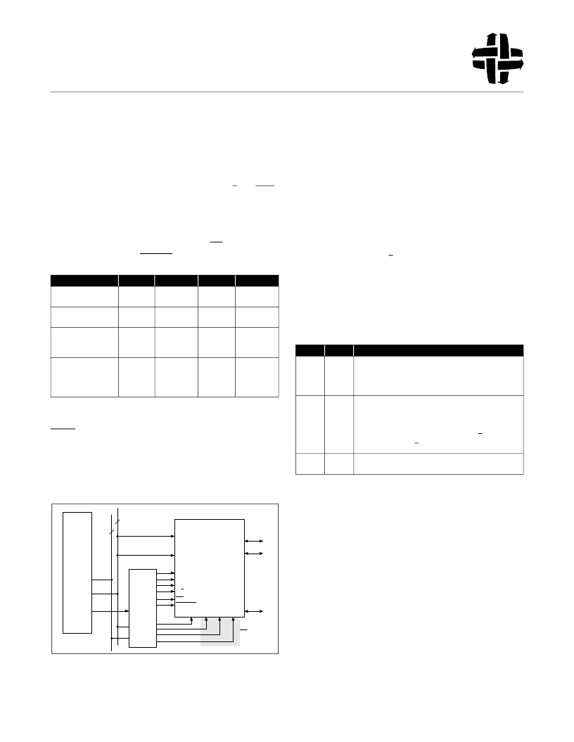
The RapidConfigure interface shown in Figure 7 is a write only
interface. Its operation is some what simlar to a memory write
cycle in a mcroprocessor system- it uses address, data and
control signals to write to the Switch Matrix SRAMcells and I/O
Port configuration registers. The Control bus, {P/
S (Port/Switch)
,
C[1:0]} defines the type of operation performed by the
RapidConfigure cycle, while the Row Address, RA[m-1:0], and
Column Address, CA[m-1:0], provide the necessary addresses
and/or data for the different operations. The value “m” is different
for different devices as shown in Table 2. WE (Write Enable)
acts as chip select while STROBE is the write strobe.
Notes:
1. The IQ compatibility mode uses the lower of the two numbers shown.
2.
Due to the requirements for compatibility with the IQ Famly
and/or
bondout restrictions, this number is lower than (# in row1 - #
in row 2) for some devices.
Figure 7. IQX RapidConfigure System Interface
In a typical system an embedded processor will compute the
required Row Address, Column Address and Control values and
apply themto the IQX device. Alternatively, these values could
be computed before hand using the I-Cube supplied
development systemsoftware (IDS100), and stored in a lookup
table.
The RapidConfigure mode is enabled or disabled by correctly
setting the RC
bit
in the Mode Control Register. Table 3 shows
the different RapidConfigure options, depending on the values of
the “RC” and “RM”
bits
in the Mode Control Register. During
hardware reset (TRST*= 0) these bits are set to the signal value
on the “RCE” (RapidConnect Enable)
pin
. The values of these
bits
can then be changed if required using the JTAG serial
interface. Note that the “P/
S
” signal shown in Figure 7 is required
only if the RapidConfigure interface is used for changing I/O Port
configuration, i.e., when RC
bit
= 1 and RM
bit
= 1. The pin is
available for use as signal I/O pin (I/O Port) when RM bit = 0.
Table 8 summarizes the different options. Compatibility with the
IQ famly devices is achieved by connecting the RCE
pin
to V
SS
on the board.
The user must ensure that the I/O Ports used for the
RapidConfigure interface are in the Input (IN) mode and any
connections to corresponding signal lines in the Switch Matrix
are cleared before attempting to configure the device using this
interface. During device reset, the I/O Ports used for the
RapidConfigure interface are set to the required Input (IN) and
all connections in the Switch Matrix are cleared.
1.4.1 Switch Matrix Connection Changes
As indicated earlier, the Switch Matrix SRAMcells that control
the connections among I/O Ports forma two dimensional array.
Every SRAM cell location in the Switch Matrix that is being
written to is uniquely identified by its Row (or Word) Address and
Column (or Bit) Address. The
real
SRAM cell responsible for the
connection between two I/O Port numbers “i” and “j” on the
Feature
IQX320
320
IQX240B
240
IQX160
160
IQX128B
128
Total Number of I/O
Ports
I/O Ports Used for RC
Interface
1
Row Address and
Column Address Bus
Widths
I/O Ports whose
connections can be
changed using RC
interface
2
23 / 22
23 / 22
21/20
19/18
9
9
8
7
298
218
140
102
Table 2. RapidConfigure Interface Pin Count
CPU
BUS
Config
Control
Logic
I/O Port
C
0
C
1
P/S
WE
STROBE
TRST*
CLK
BUS
IQX
I/O Port
I/O Port
Optional
RA[m-1:0]
RCE
CA[m-1:0]
TDI TMS TCK
RC Bit RM Bit
0
Operation
0
RapidConfigure Mode is disabled. The device can only be
configured using the JTAG-based serial interface. In this
mode, the I/O Ports used for RapidConfigure Interface can
be used for as signal I/O Ports.
RapidConfigure Mode is enabled for changing Switch
Matrix connections but not for I/O Port configuration. The
I/O Ports can only be configured using the JTAG-based
serial interface.
In this mode, the signal comng fromthe P/S pin is forced
low internally. The P/S pin is available as a signal I/O Port.
RapidConfigure Mode is enabled for changing Switch
Matrix connections and I/O Port configurations.
1
0
1
1
Table 3. RapidConfigure Options
Powered by ICminer.com Electronic-Library Service CopyRight 2003
相關(guān)PDF資料 |
PDF描述 |
|---|---|
| IQX320-7PP391 | User Programmable Special Function ASIC |
| IQX320-PB416 | User Programmable Special Function ASIC |
| IR00 | ASIC |
| IR01HD224-P2 | PERIPHERAL DRIVER|1 DRIVER|CMOS|SIP|9PIN|PLASTIC |
| IR01HD420 | PERIPHERAL DRIVER|1 DRIVER|CMOS|SIP|9PIN|PLASTIC |
相關(guān)代理商/技術(shù)參數(shù) |
參數(shù)描述 |
|---|---|
| IQXO-22C-24.0 | 制造商:IQD Frequency Products 功能描述:OSCILLATOR CRYSTAL |
| IQXO-22C-32MHZ | 制造商:IQD Frequency Products 功能描述:OSCILLATOR CRYSTAL |
| IQXO-22C-4.0 | 制造商:IQD Frequency Products 功能描述:OSCILLATOR CRYSTAL |
| IQXO-22C-50.0 | 制造商:IQD Frequency Products 功能描述:OSCILLATOR CRYSTAL |
| IQXO-331-100.0MHz | 制造商:IQD Frequency Products 功能描述:CRYSTAL OSCILLATOR 100.000000MHZ |
發(fā)布緊急采購,3分鐘左右您將得到回復(fù)。