- 您現(xiàn)在的位置:買賣IC網(wǎng) > PDF目錄383109 > IMS82C55AZ (INTERSIL CORP) CMOS Programmable Peripheral Interface PDF資料下載
參數(shù)資料
| 型號: | IMS82C55AZ |
| 廠商: | INTERSIL CORP |
| 元件分類: | 微控制器/微處理器 |
| 英文描述: | CMOS Programmable Peripheral Interface |
| 中文描述: | 24 I/O, PIA-GENERAL PURPOSE, PQCC44 |
| 封裝: | ROHS COMPLIANT, PLASTIC, MS-018AC, LCC-44 |
| 文件頁數(shù): | 4/24頁 |
| 文件大小: | 502K |
| 代理商: | IMS82C55AZ |
4
FN6140.1
June 28, 2005
Group A and Group B Controls
The functional configuration of each port is programmed by
the systems software. In essence, the CPU “outputs” a
control word to the 82C55A. The control word contains
information such as “mode”, “bit set”, “bit reset”, etc., that
initializes the functional configuration of the 82C55A.
Each of the Control blocks (Group A and Group B) accepts
“commands” from the Read/Write Control logic, receives
“control words” from the internal data bus and issues the
proper commands to its associated ports.
Control Group A - Port A and Port C upper (C7 - C4)
Control Group B - Port B and Port C lower (C3 - C0)
The control word register can be both written and read as
shown in the “Basic Operation” table. Figure 4 shows the
control word format for both Read and Write operations.
When the control word is read, bit D7 will always be a logic
“1”, as this implies control word mode information.
Ports A, B, and C
The 82C55A contains three 8-bit ports (A, B, and C). All can
be configured to a wide variety of functional characteristics
by the system software but each has its own special features
or “personality” to further enhance the power and flexibility of
the 82C55A.
Port A
One 8-bit data output latch/buffer and one 8-bit data
input latch.
Port B
One 8-bit data input/output latch/buffer and one 8-bit
data input buffer.
Port C
One 8-bit data output latch/buffer and one 8-bit data
input buffer (no latch for input). This port can be divided into
two 4-bit ports under the mode control. Each 4-bit port
contains a 4-bit latch and it can be used for the control signal
output and status signal inputs in conjunction with ports A
and B.
Operational Description
Mode Selection
There are three basic modes of operation than can be
selected by the system software:
Mode 0 - Basic Input/Output
Mode 1 - Strobed Input/Output
Mode 2 - Bidirectional Bus
When the reset input goes “high”, all ports will be set to the
input mode. After the reset is removed, the 82C55A can
remain in the input mode with no additional initialization
required. The control word register will contain 9Bh. During
the execution of the system program, any of the other modes
may be selected using a single output instruction. This
allows a single 82C55A to service a variety of peripheral
devices with a simple software maintenance routine. Any
port programmed as an output port is initialized to all zeros
when the control word is written.
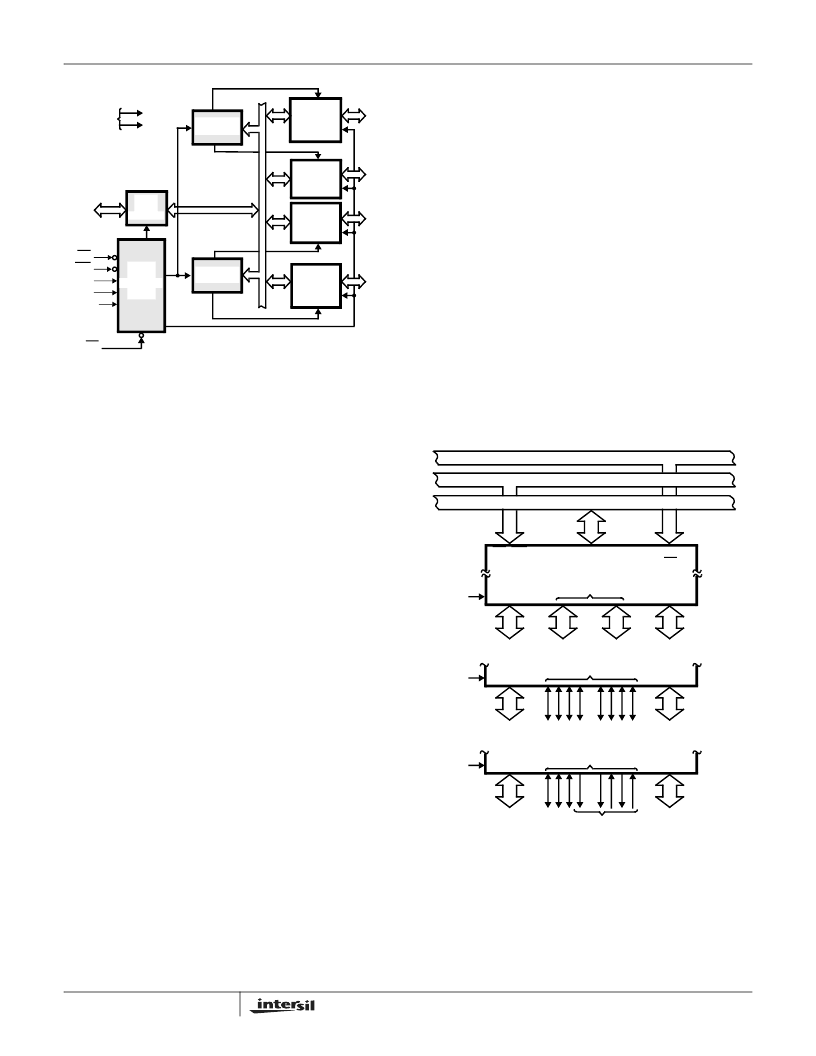
FIGURE 2. 82C55A BLOCK DIAGRAM. DATA BUS BUFFER,
READ/WRITE, GROUP A & B CONTROL LOGIC
FUNCTIONS
GROUP A
PORT A
(8)
GROUP A
PORT C
UPPER
(4)
GROUP B
PORT C
LOWER
(4)
GROUP B
PORT B
(8)
GROUP B
CONTROL
GROUP A
CONTROL
DATA
BUS
READ
WRITE
CONTROL
LOGIC
RD
WR
A1
A0
RESET
CS
D7-D0
POWER
SUPPLIES
+5V
GND
BIDIRECTIONAL
DATA BUS
I/O
PA7-
PA0
I/O
PC7-
PC4
I/O
PC3-
PC0
I/O
PB0
BUFFER
8-BIT
INTERNAL
DATA BUS
FIGURE 3. BASIC MODE DEFINITIONS AND BUS INTERFACE
DATA BUS
8
I/O
B
PB7-PB0
4
I/O
PC3-PC0
4
I/O
C
PC7-PC4
8
I/O
A
PA7-PA0
CONTROL BUS
ADDRESS BUS
RD, WR
82C55A
D7-D0
A0-A1
CS
MODE 0
8
I/O
B
PB7-PB0
CONTROL
OR I/O
C
8
I/O
A
PA7-PA0
MODE 1
CONTROL
OR I/O
8
I/O
B
PB7-PB0
C
BI-
DIRECTIONAL
A
PA7-PA0
MODE 2
CONTROL
MS82C55A, MQ82C55A
相關PDF資料 |
PDF描述 |
|---|---|
| IMS82C55AZ96 | CMOS Programmable Peripheral Interface |
| IMT17 | General purpose transistor isolated dual transistors |
| IMT2A | General purpose (dual transistors) |
| IMT3A | General purpose (dual transistors) |
| IMZ4 | General purpose transistor (dual transistors) |
相關代理商/技術參數(shù) |
參數(shù)描述 |
|---|---|
| IMS82C55AZ96 | 功能描述:外圍驅動器與原件 - PCI PERI PRG-I/O 5V 8MHZ 44PLCC INDOKI PARTPL RoHS:否 制造商:PLX Technology 工作電源電壓: 最大工作溫度: 安裝風格:SMD/SMT 封裝 / 箱體:FCBGA-1156 封裝:Tray |
| IMSA100-G17M | 制造商:未知廠家 制造商全稱:未知廠家 功能描述:Digital Filter |
| IMSA100-G21I | 制造商:未知廠家 制造商全稱:未知廠家 功能描述:Digital Filter |
| IMSA100-G21M | 制造商:未知廠家 制造商全稱:未知廠家 功能描述:Digital Filter |
| IMSA100-G21S | 制造商:未知廠家 制造商全稱:未知廠家 功能描述:Digital Filter |
發(fā)布緊急采購,3分鐘左右您將得到回復。