- 您現(xiàn)在的位置:買賣IC網(wǎng) > PDF目錄360786 > ICSXXXXYFLFT 26/SKT/TB/2R/10AVE/90:10 PDF資料下載
參數(shù)資料
| 型號: | ICSXXXXYFLFT |
| 英文描述: | 26/SKT/TB/2R/10AVE/90:10 |
| 中文描述: | 系統(tǒng)時鐘芯片的支持ATI RS400 P4TM的系統(tǒng) |
| 文件頁數(shù): | 3/19頁 |
| 文件大小: | 206K |
| 代理商: | ICSXXXXYFLFT |
3
Integrated
Circuit
Systems, Inc.
ICS951411
0891E—03/07/05
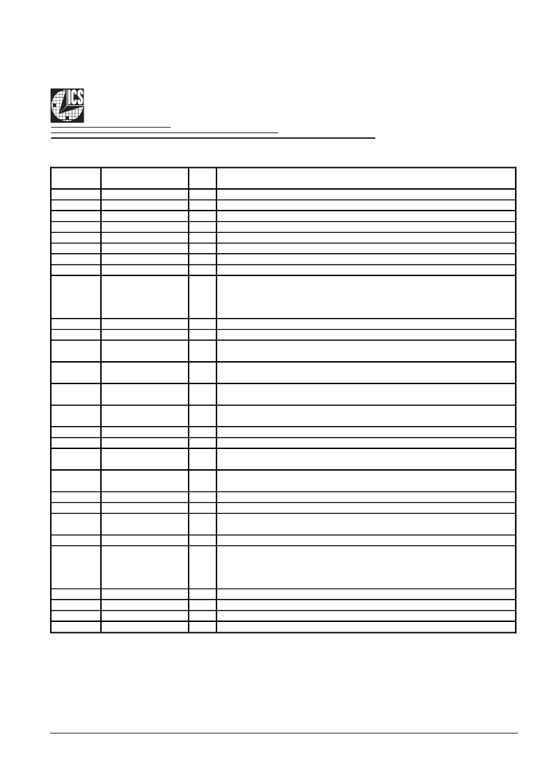
Pin Description (Continued)
PIN #
PIN NAME
PIN
TYPE
OUT Complementary clock of differential SRC clock pair.
OUT True clock of differential SRC clock pair.
PWR Ground for ATI Gclocks, nominal 3.3V
PWR Power supply ATI Gclocks, nominal 3.3V
OUT Complement clock of differential SRC clock pair.
OUT True clock of differential SRC clock pair.
PWR Supply for SRC clocks, 3.3V nominal
PWR Ground pin for the SRC outputs
DESCRIPTION
29
30
31
32
33
34
35
36
ATIGCLKC0
ATIGCLKT0
GNDATI
VDDATI
SRCCLKC0
SRCCLKT0
VDDSRC
GNDSRC
37
IREF
OUT
This pin establishes the reference current for the differential current-mode
output pairs. This pin requires a fixed precision resistor tied to ground in order
to establish the appropriate current. 475 ohms is the standard value.
38
39
GNDA
VDDA
PWR Ground pin for the PLL core.
PWR 3.3V power for the PLL core.
Complementary clock of differential pair CPU outputs. These are current mode
outputs. External resistors are required for voltage bias.
True clock of differential pair CPU outputs. These are current mode outputs.
External resistors are required for voltage bias.
Complementary clock of differential pair CPU outputs. These are current mode
outputs. External resistors are required for voltage bias.
True clock of differential pair CPU outputs. These are current mode outputs.
External resistors are required for voltage bias.
PWR Ground pin for the CPU outputs
PWR Supply for CPU clocks, 3.3V nominal
Complementary clock of differential pair CPU outputs. These are current mode
outputs. External resistors are required for voltage bias.
True clock of differential pair CPU outputs. These are current mode outputs.
External resistors are required for voltage bias.
IN
Stops all CPUCLK, except those set to be free running clocks
PWR Ground pin for the PCI outputs
FS Table select latch input pin / 3.3V PCI clock output.
0 = CK410 FS Table, 1 = CK409 FS Table
PWR Power supply for PCI clocks, nominal 3.3V
40
CPUCLKC2_ITP
OUT
41
CPUCLKT2_ITP
OUT
42
CPUCLKC1
OUT
43
CPUCLKT1
OUT
44
45
GNDCPU
VDDCPU
46
CPUCLKC0
OUT
47
CPUCLKT0
OUT
48
49
*CPU_STOP#
GNDPCI
50
**CK410#/PCICLK0
I/O
51
VDDPCI
52
**TEST_SEL/REF2
I/O
TEST_SEL: latched input to select TEST MODE / 14.318 MHz reference clock.
1 = All outputs are CK410 REF/N test mode
0 = All outputs behave normally.
53
54
55
56
**FS_B/REF1
**FS_A/REF0
GND
VDDREF
I/O
I/O
PWR Ground pin.
PWR Ref, XTAL power supply, nominal 3.3V
Frequency select latch input pin / 14.318 MHz reference clock.
Frequency select latch input pin / 14.318 MHz reference clock.
相關(guān)PDF資料 |
PDF描述 |
|---|---|
| ICSXXXXYGLFT | System Clock Chip for ATI RS400 P4TM-based Systems |
| ICS951412YGLFT | System Clock Chip for ATI RS480 K8-based Systems |
| ICS951412 | 16-Bit Buffers/Drivers With 3-State Outputs 48-TSSOP -40 to 85 |
| ICS951412YFLFT | System Clock Chip for ATI RS480 K8-based Systems |
| ICS951601 | General Purpose Frequency Timing Generator |
相關(guān)代理商/技術(shù)參數(shù) |
參數(shù)描述 |
|---|---|
| ICSXXXXYGLFT | 制造商:ICS 制造商全稱:ICS 功能描述:System Clock Chip for ATI RS400 P4TM-based Systems |
| IC-SY WK1D | 制造商:LASER COMPONENTS 功能描述:DEVELOPMENT KIT LD DRIVER |
| ICT-075-A-10.0-G | 制造商:Interconnect Devices Inc (IDI) 功能描述:contact probe, .075' CTR 3 amp, concave 90 deg |
| ICT-075-A-10-G S/C | 功能描述:觸點探頭 .075’ CTR 3AMP PROBE HEADED 90 DEG CNCAVE RoHS:否 制造商:IDI 類型:Probes 尖端類型:Spherical Radius 長度:8.26 mm 電流額定值:10 A 彈力:2.3 oz 行程:1.52 mm 系列:101050 |
| ICT-075-A-5-G | 制造商:Interconnect Devices Inc (IDI) 功能描述:SPRING CONTACT PROBE |
發(fā)布緊急采購,3分鐘左右您將得到回復(fù)。