- 您現(xiàn)在的位置:買賣IC網(wǎng) > PDF目錄384479 > ICS1702 (Electronic Theatre Controls, Inc.) QuickSaver Charge Controller for Nickel-Cadmium and Nickel-Metal Hydride Batteries PDF資料下載
參數(shù)資料
| 型號: | ICS1702 |
| 廠商: | Electronic Theatre Controls, Inc. |
| 英文描述: | QuickSaver Charge Controller for Nickel-Cadmium and Nickel-Metal Hydride Batteries |
| 中文描述: | QuickSaver充電控制器的鎳鎘和鎳氫電池 |
| 文件頁數(shù): | 20/28頁 |
| 文件大?。?/td> | 466K |
| 代理商: | ICS1702 |
第1頁第2頁第3頁第4頁第5頁第6頁第7頁第8頁第9頁第10頁第11頁第12頁第13頁第14頁第15頁第16頁第17頁第18頁第19頁當前第20頁第21頁第22頁第23頁第24頁第25頁第26頁第27頁第28頁
20
ICS1702
With the batteries removed, the current source must be capable of
raising the voltage at the VIN pin above the voltage at the OPREF
pin to ensure proper polling. With the batteries installed, the
current source overshoot characteristics when turned on and off
must not cause the voltage at the VIN pin to exceed the voltage at
the OPREF pin. If the voltage at OPREF exceeds the voltage at
VIN when a charge pulse is applied or removed, the polling feature
will be activated.
PC Board Design Considerations
It is very important that care be taken to minimize noise coupling
and ground bounce. In addition, wires and connectors can add
significant resistance and inductance to the charge and discharge
circuits. When designing the printed circuit board, make sure
ground and power traces are wide and bypass capacitors are used
right at the controller. Use separate grounds for the signal, charge
and discharge circuits. Separate ground planes on the component
side of the PC board are recommended. Be sure to connect these
grounds together at the negative lead of the battery only. For the
discharge circuit, keep the physical separation between power and
return (ground) to a minimum to minimize field radiation effects.
This precaution is also applicable to the constant current source,
particularly if it is a switch mode type. Keep the
ICS1702
and the
constant current source control circuits outside the power and
return loop described above. These precautions will prevent high
circulating currents and coupled noise from disturbing normal
operation.
Selecting the Appropriate Termination Method
In general, the voltage slope termination method works best for
equipment where the battery is fast charged with the equipment off
or the battery is removed from the equipment for fast charge. The
temperature slope and maximum temperature termination methods
are for equipment that must remain operative while the battery is
fast charged.
Applications Information
To ensure proper operation of the
ICS1702
, external components
must be properly selected. The external current source used must
meet several important criteria to ensure optimal performance of
the charging system. The charging current should be constant when
using voltage slope termination. The current may vary when using
temperature slope termination.
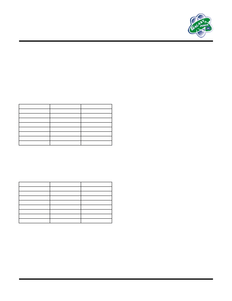
VIN and OPREF Divider Resistors
Figure 15 shows a typical application using the
ICS1702
. R1
through R4 must be carefully selected to ensure that battery
detection and voltage termination methods operate properly.
R1 and R2 are selected to scale the battery voltage down to the
voltage of one cell. The following table shows some typical values.
Additional information is available in the
Voltage Input
section.
Cells
1
2
3
4
5
6
7
8
R1
Short
2.0k
2.0k
3.0k
12k
10k
12k
9.1k
R2
Open
2.0k
1.0k
1.0k
3.0k
2.0k
2.0k
1.3k
If using voltage slope termination, the current source should
prevent ripple voltage from appearing on the battery. The effects of
ripple on the battery voltage may interfere with proper operation
when using the voltage slope method.
R3 and R4 are used to set the open circuit (no battery) reference
voltage on the OPREF pin. The function of this pin is discussed in
the
Open Circuit Reference
section.
V
OPREF
1.86 V
1.92 V
1.97 V
2.00 V
2.03 V
2.10 V
2.14 V
2.22 V
R3
2.2k
2.4k
2.0k
3.0k
2.2k
1.8k
2.4k
3.0k
R4
1.3k
1.5k
1.3k
2.0k
1.5k
1.3k
1.8k
2.4k
相關(guān)PDF資料 |
PDF描述 |
|---|---|
| ICS1702M | QuickSaver Charge Controller for Nickel-Cadmium and Nickel-Metal Hydride Batteries |
| ICS662-03 | HDTV Audio/Video Clock Source |
| ICS66203 | HDTV Audio/Video Clock Source |
| ICS94222 | Programmable System Frequency Generator for PII/III⑩ |
| ICT-xxx | TRANSIENT ABSORPTION ZENER |
相關(guān)代理商/技術(shù)參數(shù) |
參數(shù)描述 |
|---|---|
| ICS1702M | 制造商:未知廠家 制造商全稱:未知廠家 功能描述:QuickSaver Charge Controller for Nickel-Cadmium and Nickel-Metal Hydride Batteries |
| ICS1702MT | 制造商:未知廠家 制造商全稱:未知廠家 功能描述:QuickSaver Charge Controller for Nickel-Cadmium and Nickel-Metal Hydride Batteries |
| ICS1702N | 制造商:未知廠家 制造商全稱:未知廠家 功能描述:QuickSaver Charge Controller for Nickel-Cadmium and Nickel-Metal Hydride Batteries |
| ICS1705 | 制造商:未知廠家 制造商全稱:未知廠家 功能描述:Analog IC |
| ICS1708 | 制造商:未知廠家 制造商全稱:未知廠家 功能描述:QuickSaver Charge Control IC for Nickel-Cadmium and Nickel-Metal Hydride Batteries |
發(fā)布緊急采購,3分鐘左右您將得到回復。