- 您現(xiàn)在的位置:買賣IC網(wǎng) > PDF目錄1923 > HSP43168JC-33Z (Intersil)IC FIR FILTER DUAL 84-PLCC PDF資料下載
參數(shù)資料
| 型號: | HSP43168JC-33Z |
| 廠商: | Intersil |
| 文件頁數(shù): | 7/25頁 |
| 文件大小: | 0K |
| 描述: | IC FIR FILTER DUAL 84-PLCC |
| 標(biāo)準(zhǔn)包裝: | 15 |
| 濾波器類型: | FIR |
| 濾波器數(shù): | 2 |
| 電源電壓: | 4.75 V ~ 5.25 V |
| 安裝類型: | 表面貼裝 |
| 封裝/外殼: | 84-LCC(J 形引線) |
| 供應(yīng)商設(shè)備封裝: | 84-PLCC(29.21x29.21) |
| 包裝: | 管件 |
15
FN2808.12
July 27, 2009
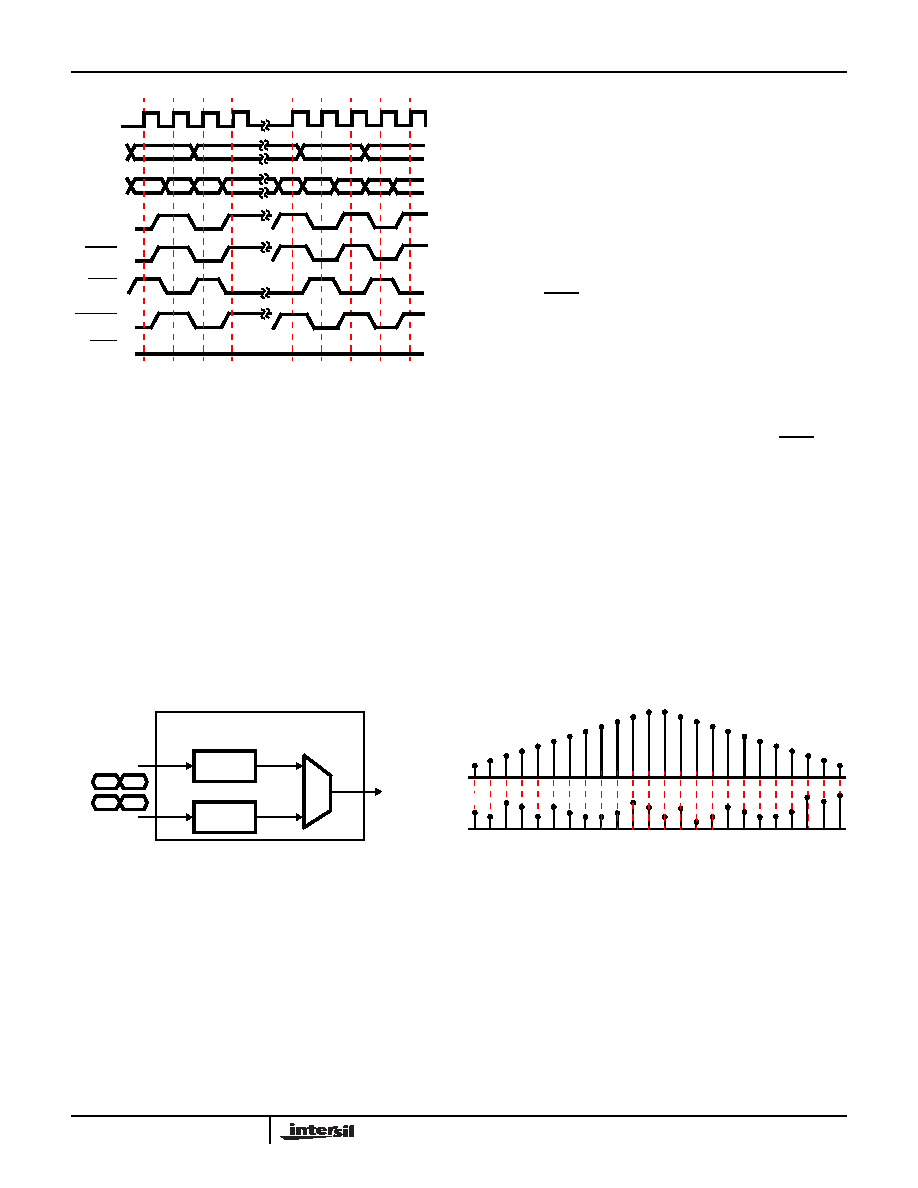
Example 4: Even-Tap Decimating Filter Example
The HSP43168 supports filtering applications requiring
decimation to 16. In these applications the output data rate is
reduced by a factor of N. As a result, N clock cycles can be
used for the computation of the filter output. For example,
each FIR cell can calculate 8 symmetric or 4 asymmetric
taps in one clock. If the application requires decimation by
two, the filter output can be calculated over two clocks thus,
boosting the number of taps per FIR cell to 16 symmetric or
8 asymmetric. For this example, each FIR cell is configured
as an independent 24-tap decimate x3 filter. Again, the data
flow diagrams show only one of the FIR cells shown in
Figure 15.
The alignment of data relative to the 24 filter coefficients for
a particular output is depicted graphically in Figure 16. As in
previous examples, the HSP43168 implements the filtering
operation by summing data samples prior to multiplication by
the common coefficient. In this example an output is required
every third CLK which allows 3 CLKs for computation. On
each CLK, one of three sets of coefficients are used to
calculate 8 of the filter taps. The Block Diagrams in Figure 17
show the data flow and accumulator output for the
data/coefficient alignment in Figure 16.
Proper data and coefficient alignment is achieved by
asserting TXFR once every three CLKs to switch the LIFOs
which are being read and written. This has the effect of
feeding blocks of three samples into the backward shifting
decimation path which are reversed in sample order. In
addition, ACCEN is deasserted once every three clocks to
allow accumulation over three CLKs. The three sets of
coefficients required in the calculation of a 24-tap symmetric
filter are cycled through using CSEL0-4. The timing
relationship between the CSEL0-4, ACCEN, and TXFR are
shown in Figure 18.
To operate in this mode the Dual is configured by writing 1d2
to Address 000H via the microprocessor interface, CIN0-9,
A0-8, and WR. Data reversal must be enabled see (Table 2).
The 12 unique coefficients for this example are stored as
three sets of coefficients for either FIR cell. For FIR A, the
coefficients are loaded into the Coefficient Bank by writing
C2, C5, C8, C11, C1, C4, C7, C10, C0, C3, C6, and C9 to
Address [100H, 101H, 102H, 103H], CSEL = 0; [108H,
109H, 10aH, 10bH], CSEL = 1; [110H, 111H, 112H, and
113H], CSEL = 2, respectively.
0
1
2
3
13
14
15
16
X0
X1
10
1
0
1
0
X6
X7
X8
CLK
INA0-9
CSEL0-4
ACCEN
SHFTEN
RVRS
FWRD
0
NOTE: CLK is 2X data rate.
FIGURE 14. CONTROL TIMING FOR 8-TAP ASYMMETRIC
FILTER
TXFR
(TIED LOW)
(NOTE)
FIGURE 15. EVEN-TAP DECIMATING FILTER, 24-TAP DEC = 3
FIGURE 16. DATA/COEFFICIENT ALIGNMENT FOR 24-TAP
DECIMATE BY 3 FIR FILTER
HSP43168
INA0-9
INB0-9
OUT9-27
FIR A
FIR B
M
U
X
EVEN-TAP DECIMATING
AA
BB
23 22 21 20 19 18 17 16 15 14 13 12 11 10 9 8 7
6 5 4 3 2 1 0
C11
C10
C9
C8
C7
C6
C5
C4
C3
C2
C1
C0
h(n)
C11C10
C9 C8
C7 C6
C5 C4
C3 C2
C1 C0
24-TAPS
x(n)
HSP43168
相關(guān)PDF資料 |
PDF描述 |
|---|---|
| HSP43216JC-52Z | IC HALFBAND FILTER 84-PLCC |
| HSP43220JC-33Z | IC DECIMATING DGTL FILTER 84PLCC |
| IA188EM-PTQ100I-R-03 | IC MCU 8/16BIT 40MHZ 100TQFP |
| IA188ES-PTQ100I-R-03 | IC MCU 8/16BIT 40MHZ 100TQFP |
| IA6805E2PLC44IR0 | IC MCU 8BIT 5MHZ 44PLCC |
相關(guān)代理商/技術(shù)參數(shù) |
參數(shù)描述 |
|---|---|
| HSP43168JC-40 | 制造商:Rochester Electronics LLC 功能描述:DUAL DIGITAL FILTER 84 PLCC, 40MHZ, COMM - Bulk |
| HSP43168JC-45 | 制造商:Rochester Electronics LLC 功能描述:DUAL DIGITAL FILTER 84 PLCC, 45MHZ, COMM - Bulk |
| HSP43168JC-45S5001 | 制造商:Rochester Electronics LLC 功能描述:- Bulk |
| HSP43168JI-40 | 制造商:Rochester Electronics LLC 功能描述:DUAL DIGITAL FILTER 84 PLCC 40MHZ,INDUSTRIAL TEMP - Bulk |
| HSP43168VC-33 | 制造商:Rochester Electronics LLC 功能描述:DUAL DIGITAL FILTER 100 PQFP, 33MHZ, COMM - Bulk 制造商:Harris Corporation 功能描述: 制造商:Intersil Corporation 功能描述: |
發(fā)布緊急采購,3分鐘左右您將得到回復(fù)。