- 您現(xiàn)在的位置:買賣IC網(wǎng) > PDF目錄370661 > HPC3130APBM (Texas Instruments, Inc.) PCI Bus Interface/Controller PDF資料下載
參數(shù)資料
| 型號: | HPC3130APBM |
| 廠商: | Texas Instruments, Inc. |
| 英文描述: | PCI Bus Interface/Controller |
| 中文描述: | PCI總線接口/控制器 |
| 文件頁數(shù): | 28/41頁 |
| 文件大小: | 537K |
| 代理商: | HPC3130APBM |
第1頁第2頁第3頁第4頁第5頁第6頁第7頁第8頁第9頁第10頁第11頁第12頁第13頁第14頁第15頁第16頁第17頁第18頁第19頁第20頁第21頁第22頁第23頁第24頁第25頁第26頁第27頁當前第28頁第29頁第30頁第31頁第32頁第33頁第34頁第35頁第36頁第37頁第38頁第39頁第40頁第41頁

HPC3130A
PCI HOT PLUG CONTROLLER
SCPS055 – NOVEMBER 1999
28
POST OFFICE BOX 655303
DALLAS, TEXAS 75265
configuration and control registers (continued)
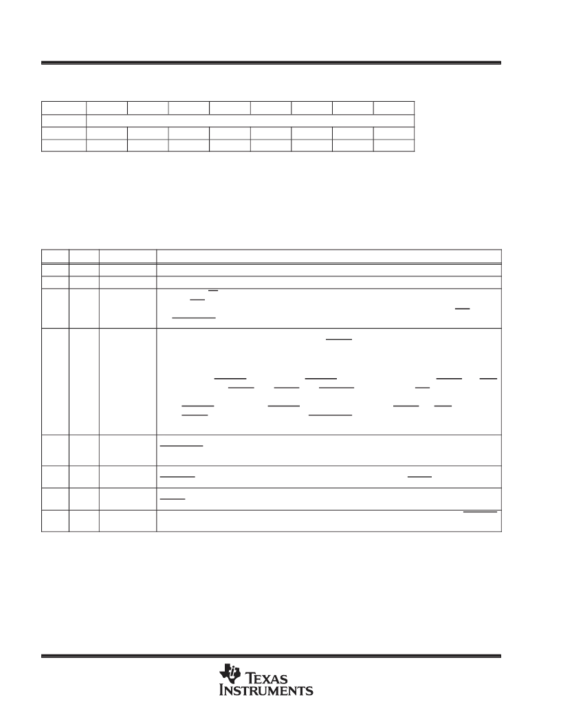
hot-plug slot control register
Bit
7
6
5
4
3
2
1
0
Name
Hot-plug slot control register
Type
R
R
R/W
R/W
R/W
R/W
R/W
R/W
Default
0
0
1
0
1
1
0
1
Register:
Type:
Offset:
Default:
Description:
Hot-plug slot control
Read-only, Read/Write
02 (slot 0), 0Ah (slot 1), 12h (slot 2), 1Ah (slot 3)
2Dh
This register applies power, resets, and provides general control of a hot-plug slot
connection to the system PCI bus.
Table 10. Hot-Plug Slot Control Register
BIT
TYPE
NAME
FUNCTION
7
R
RSVD
Reserved. This bit returns 0 when read.
6
R
RSVD
Reserved. This bit returns 0 when read.
5
R/W
SLTPWR_CTL
Slot power On/Off control. The data written to this bit represents the logical value of the data to drive the
PWRON/OFF output and is used to control the power state of a hot-plug slot. If the PROTECTEN bit in the
general configuration register is set to 1, then a logic high can only be driven by the PWRON/OFF output if
the DETECT[1:0] inputs are low.
4
R/W
BUS_CTL
PCI bus CBT-switch control. When manual sequencing is enabled, then the value written to this bit
represents the logical value of the data driven to the BUSON output, and it is used to connect/disconnect a
hot-plug slot to/from the PCI bus.
If an auto sequencing mode is enabled in the general configuration register, then this bit functions as follows:
1 = By setting this bit, the hot-plug slot gets disconnected from the PCI bus. This is accomplished by
asserting IDLEREQ, then waiting for IDLEGNT assertion and deassertion of FRAME and IRDY
before driving BUSON high, CLKON high, REQ64ON low, and PWRON/OFF low.
0 = By clearing this bit, the hot-plug slot gets connected to the PCI bus. This is accomplished by asserting
IDLEREQ, then waiting for IDLEGNT assertion and deassertion of FRAME and IRDY before driving
BUSON low. Also verifies assertion of DETECT[1:0] if the protection enable bit is enabled in the
general configuration register.
3
R/W
SLOTREQ64
Slot request 64-bit control. The data written to this bit represents the logical value of the data driven to the
SLOTREQ64 output and is used during reset of a slot after power is applied. This input indicates to an option
card whether or not it is connected to a 64-bit slot.
2
R/W
REQ64_O
REQ64 CBT switch control. The data written to this bit represents the logical value of the data driven to the
REQ64ON output and is used to control the CBT switch that implements the REQ64 PCI signal.
1
R/W
CLKON_O
CLKON CBT switch control. The data written to this bit represents the logical value of the data driven to the
CLKON output and is used to control the clock driver to the hot-plug slot.
0
R/W
SLOTRST_O
Slot reset control. The data written to this bit represents the logical value of the data driven to the SLOTRST
output and is used to reset a hot-plug slot after power is applied.
相關PDF資料 |
PDF描述 |
|---|---|
| HPC3130APBKLOW-PROFILEQUA | DIODE ZENER DUAL COMMON-CATHODE 300mW 33Vz 5mA-Izt 0.0606 0.1uA-Ir 25 SOT-23 3K/REEL |
| HPC3130PGELOW-PROFILEQUAD | PCI HOT PLUG CONTROLLER |
| HPC3130PBMQUADFLAT | PCI HOT PLUG CONTROLLER |
| HPC3130PBKLOW-PROFILEQUAD | PCI HOT PLUG CONTROLLER |
| HPC43100VHG30 | 16-Bit Microcontroller |
相關代理商/技術參數(shù) |
參數(shù)描述 |
|---|---|
| HPC3130APBMQUADFLAT | 制造商:TI 制造商全稱:Texas Instruments 功能描述:PCI HOT PLUG CONTROLLER |
| HPC3130APGE | 功能描述:外圍驅(qū)動器與原件 - PCI HOT PLUG CONTROLLER RoHS:否 制造商:PLX Technology 工作電源電壓: 最大工作溫度: 安裝風格:SMD/SMT 封裝 / 箱體:FCBGA-1156 封裝:Tray |
| HPC3130APGEG4 | 功能描述:外圍驅(qū)動器與原件 - PCI HOT PLUG CONTROLLER RoHS:否 制造商:PLX Technology 工作電源電壓: 最大工作溫度: 安裝風格:SMD/SMT 封裝 / 箱體:FCBGA-1156 封裝:Tray |
| HPC3130APGELOW-PROFILEQUA | 制造商:TI 制造商全稱:Texas Instruments 功能描述:PCI HOT PLUG CONTROLLER |
| HPC3130PBK | 功能描述:外圍驅(qū)動器與原件 - PCI HOT PLUG CONTROLLER RoHS:否 制造商:PLX Technology 工作電源電壓: 最大工作溫度: 安裝風格:SMD/SMT 封裝 / 箱體:FCBGA-1156 封裝:Tray |
發(fā)布緊急采購,3分鐘左右您將得到回復。