- 您現(xiàn)在的位置:買賣IC網(wǎng) > PDF目錄296101 > HGTP12N60C3_NL (FAIRCHILD SEMICONDUCTOR CORP) 24A,600V, UFS Series N-Channel IGBTs PDF資料下載
參數(shù)資料
| 型號: | HGTP12N60C3_NL |
| 廠商: | FAIRCHILD SEMICONDUCTOR CORP |
| 元件分類: | IGBT 晶體管 |
| 英文描述: | 24A,600V, UFS Series N-Channel IGBTs |
| 中文描述: | 24 A, 600 V, N-CHANNEL IGBT, TO-220AB |
| 文件頁數(shù): | 2/7頁 |
| 文件大?。?/td> | 172K |
| 代理商: | HGTP12N60C3_NL |
2001 Fairchild Semiconductor Corporation
HGTP12N60C3, HGT1S12N60C3S Rev. B
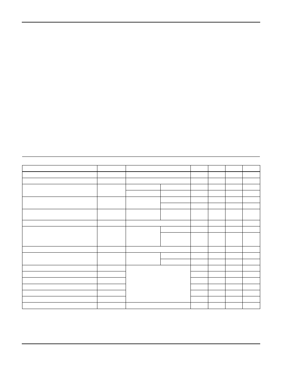
Absolute Maximum Ratings TC = 25oC, Unless Otherwise Specified
HGTP12N60C3, HGT1S12N60C3S
UNITS
Collector to Emitter Voltage . . . . . . . . . . . . . . . . . . . . . . . . . . . . . . . . . . . . . . . . . . . . . . BVCES
600
V
Collector Current Continuous
At TC = 25
oC . . . . . . . . . . . . . . . . . . . . . . . . . . . . . . . . . . . . . . . . . . . . . . . . . . . . . . . . . I
C25
24
A
At TC = 110
oC . . . . . . . . . . . . . . . . . . . . . . . . . . . . . . . . . . . . . . . . . . . . . . . . . . . . . . . I
C110
12
A
Collector Current Pulsed (Note 1) . . . . . . . . . . . . . . . . . . . . . . . . . . . . . . . . . . . . . . . . . . . ICM
96
A
Gate to Emitter Voltage Continuous. . . . . . . . . . . . . . . . . . . . . . . . . . . . . . . . . . . . . . . . . VGES
±20
V
Gate to Emitter Voltage Pulsed . . . . . . . . . . . . . . . . . . . . . . . . . . . . . . . . . . . . . . . . . . . . VGEM
±30
V
Switching Safe Operating Area at TJ = 150
oC (Figure 14) . . . . . . . . . . . . . . . . . . . . . . SSOA
24A at 600V
Power Dissipation Total at TC = 25
oC . . . . . . . . . . . . . . . . . . . . . . . . . . . . . . . . . . . . . . . . . P
D
104
W
Power Dissipation Derating TC > 25
oC . . . . . . . . . . . . . . . . . . . . . . . . . . . . . . . . . . . . . . . . . .
0.83
W/oC
Reverse Voltage Avalanche Energy . . . . . . . . . . . . . . . . . . . . . . . . . . . . . . . . . . . . . . . .
EARV
100
mJ
Operating and Storage Junction Temperature Range . . . . . . . . . . . . . . . . . . . . . . . . TJ, TSTG
-40 to 150
oC
Maximum Lead Temperature for Soldering . . . . . . . . . . . . . . . . . . . . . . . . . . . . . . . . . . . . . TL
260
oC
Short Circuit Withstand Time (Note 2) at VGE = 15V. . . . . . . . . . . . . . . . . . . . . . . . . . . . . . tSC
4
s
Short Circuit Withstand Time (Note 2) at VGE = 10V. . . . . . . . . . . . . . . . . . . . . . . . . . . . . . tSC
13
s
CAUTION: Stresses above those listed in “Absolute Maximum Ratings” may cause permanent damage to the device. This is a stress only rating and operation of the
device at these or any other conditions above those indicated in the operational sections of this specification is not implied.
NOTES:
1. Repetitive Rating: Pulse width limited by maximum junction temperature.
2. VCE(PK) = 360V, TJ = 125
oC, R
G = 25.
Electrical Specifications
TC = 25
oC, Unless Otherwise Specified
PARAMETER
SYMBOL
TEST CONDITIONS
MIN
TYP
MAX
UNITS
Collector to Emitter Breakdown Voltage
BVCES
IC = 250A, VGE = 0V
600
-
V
Emitter-Collector Breakdown Voltage
BVECS
IC = 10mA, VGE = 0V
24
30
-
V
Collector to Emitter Leakage Current
ICES
VCE = BVCES
TC = 25
oC
-
250
A
VCE = BVCES
TC = 150
oC-
-
1.0
mA
Collector to Emitter Saturation Voltage
VCE(SAT)
IC = IC110,
VGE = 15V
TC = 25
oC
-
1.65
2.0
V
TC = 150
oC
-
1.85
2.2
V
Gate to Emitter Threshold Voltage
VGE(TH)
IC = 250A,
VCE = VGE
TC = 25
oC3.0
5.0
6.0
V
Gate to Emitter Leakage Current
IGES
VGE = ±20V
-
±100
nA
Switching SOA
SSOA
TJ = 150
oC
RG = 25
VGE = 15V
L = 100
H
VCE(PK) = 480V
80
-
A
VCE(PK) = 600V
24
-
A
Gate to Emitter Plateau Voltage
VGEP
IC = IC110, VCE = 0.5 BVCES
-7.6
-
V
On-State Gate Charge
QG(ON)
IC = IC110,
VCE = 0.5 BVCES
VGE = 15V
-
48
55
nC
VGE = 20V
-
62
71
nC
Current Turn-On Delay Time
td(ON)I
TJ = 150
oC,
ICE = IC110,
VCE(PK) = 0.8 BVCES,
VGE = 15V,
RG = 25,
L = 100
H
-14-
ns
Current Rise Time
trI
-16-
ns
Current Turn-Off Delay Time
td(OFF)I
-
270
400
ns
Current Fall Time
tfI
-
210
275
ns
Turn-On Energy
EON
-
380
-
J
Turn-Off Energy (Note 3)
EOFF
-
900
-
J
Thermal Resistance
RθJC
--
1.2
oC/W
NOTE:
3. Turn-Off Energy Loss (EOFF) is defined as the integral of the instantaneous power loss starting at the trailing edge of the input pulse and ending
at the point where the collector current equals zero (ICE = 0A). The HGTP12N60C3 and HGT1S12N60C3S were tested per JEDEC standard
No. 24-1 Method for Measurement of Power Device Turn-Off Switching Loss. This test method produces the true total Turn-Off Energ y Loss.
Turn-On losses include diode losses.
HGTP12N60C3, HGT1S12N60C3S
相關(guān)PDF資料 |
PDF描述 |
|---|---|
| HGTP12N60C3D_NL | 24A, 600V, UFS Series N-Channel IGBT with Anti-Parallel Hyperfast Diodes |
| HGTP20N60A4_NL | 600V, SMPS Series N-Channel IGBTs |
| HGTP2N120CN_NL | 13A, 1200V, NPT Series N-Channel IGBT |
| HGTP3N60A4_NL | 600V, NPT Series N-Channel IGBT |
| HGTP3N60A4D_NL | 600V, SMPS Series N-Channel IGBT with Anti-Parallel Hyperfast Diode |
相關(guān)代理商/技術(shù)參數(shù) |
參數(shù)描述 |
|---|---|
| HGTP12N60C3R | 制造商:Rochester Electronics LLC 功能描述:- Bulk |
| HGTP12N60D1 | 制造商:Harris Corporation 功能描述: |
| HGTP14N0FVLR4600 | 制造商:Rochester Electronics LLC 功能描述:- Bulk |
| HGTP14N36G3VL | 功能描述:IGBT 晶體管 14a 380V Logic Level RoHS:否 制造商:Fairchild Semiconductor 配置: 集電極—發(fā)射極最大電壓 VCEO:650 V 集電極—射極飽和電壓:2.3 V 柵極/發(fā)射極最大電壓:20 V 在25 C的連續(xù)集電極電流:150 A 柵極—射極漏泄電流:400 nA 功率耗散:187 W 最大工作溫度: 封裝 / 箱體:TO-247 封裝:Tube |
| HGTP14N37G3VL | 功能描述:IGBT 晶體管 14A 370V N-Ch RoHS:否 制造商:Fairchild Semiconductor 配置: 集電極—發(fā)射極最大電壓 VCEO:650 V 集電極—射極飽和電壓:2.3 V 柵極/發(fā)射極最大電壓:20 V 在25 C的連續(xù)集電極電流:150 A 柵極—射極漏泄電流:400 nA 功率耗散:187 W 最大工作溫度: 封裝 / 箱體:TO-247 封裝:Tube |
發(fā)布緊急采購,3分鐘左右您將得到回復(fù)。