- 您現(xiàn)在的位置:買賣IC網(wǎng) > PDF目錄376803 > DM93L01 PDF資料下載
參數(shù)資料
| 型號(hào): | DM93L01 |
| 文件頁數(shù): | 15/158頁 |
| 文件大小: | 2668K |
| 代理商: | DM93L01 |
第1頁第2頁第3頁第4頁第5頁第6頁第7頁第8頁第9頁第10頁第11頁第12頁第13頁第14頁當(dāng)前第15頁第16頁第17頁第18頁第19頁第20頁第21頁第22頁第23頁第24頁第25頁第26頁第27頁第28頁第29頁第30頁第31頁第32頁第33頁第34頁第35頁第36頁第37頁第38頁第39頁第40頁第41頁第42頁第43頁第44頁第45頁第46頁第47頁第48頁第49頁第50頁第51頁第52頁第53頁第54頁第55頁第56頁第57頁第58頁第59頁第60頁第61頁第62頁第63頁第64頁第65頁第66頁第67頁第68頁第69頁第70頁第71頁第72頁第73頁第74頁第75頁第76頁第77頁第78頁第79頁第80頁第81頁第82頁第83頁第84頁第85頁第86頁第87頁第88頁第89頁第90頁第91頁第92頁第93頁第94頁第95頁第96頁第97頁第98頁第99頁第100頁第101頁第102頁第103頁第104頁第105頁第106頁第107頁第108頁第109頁第110頁第111頁第112頁第113頁第114頁第115頁第116頁第117頁第118頁第119頁第120頁第121頁第122頁第123頁第124頁第125頁第126頁第127頁第128頁第129頁第130頁第131頁第132頁第133頁第134頁第135頁第136頁第137頁第138頁第139頁第140頁第141頁第142頁第143頁第144頁第145頁第146頁第147頁第148頁第149頁第150頁第151頁第152頁第153頁第154頁第155頁第156頁第157頁第158頁
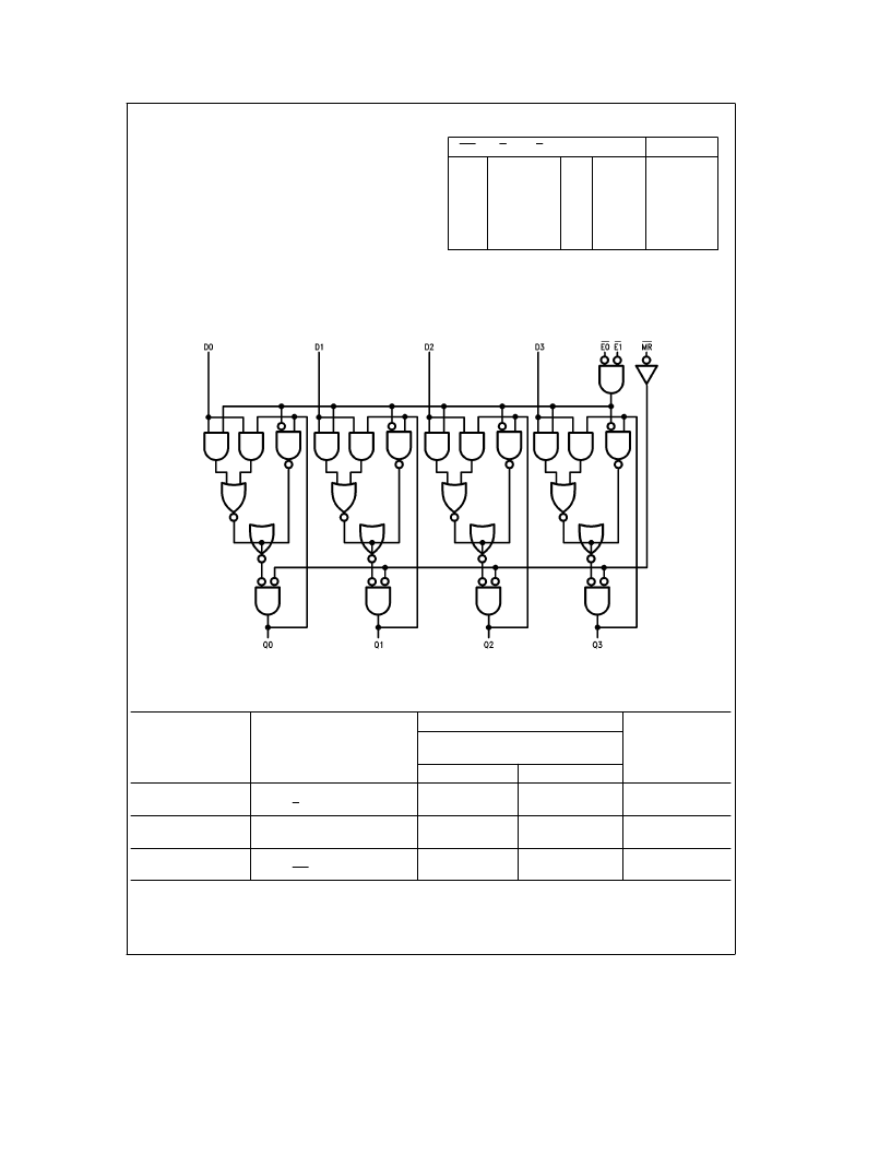
Functional Description
Data can be entered into the latch when both of the enable
inputs are LOW. As long as this logic condition exists, the
output of the latch will follow the input. If either of the enable
inputs goes HIGH, the data present in the latch at that time
is held in the latch and is no longer affected by data input.
The master reset overrides all other input conditions and
forces the outputs of all the latches LOW when a LOW sig-
nal is applied to the Master Reset input.
Truth Table
MR
E0
E1
D
Qn
Operation
H
H
H
L
L
L
L
L
H
L
H
X
L
H
Data Entry
Data Entry
Hold
Qn
b
1
H
H
L
H
H
X
L
H
X
X
X
X
Qn
b
1
Qn
b
1
L
Hold
Hold
Reset
Q
n
b
1
e
Previous Output State
Q
n
e
Present Output State
H
e
HIGH Voltage Level
L
e
LOW Voltage Level
X
e
Immaterial
Logic Diagram
TL/F/10208–3
Switching Characteristics
V
CC
e a
5.0V, T
A
e a
25
§
C (See Section 5 for test waveforms and output load.)
9308
Symbol
Parameter
C
L
e
15 pF
R
L
e
400
X
Units
Min
Max
t
PLH
t
PHL
Propagation Delay
En to Qn
30
22
ns
t
PLH
t
PHL
Propagation Delay
Dn to Qn
15
18
ns
t
PHL
Propagation Delay
MR to Qn
22
ns
3
相關(guān)PDF資料 |
PDF描述 |
|---|---|
| DM93L08 | |
| DM93L09 | |
| DM93L10 | |
| DM93L12 | |
| DM93L16 | |
相關(guān)代理商/技術(shù)參數(shù) |
參數(shù)描述 |
|---|---|
| DM93L08 | 制造商:未知廠家 制造商全稱:未知廠家 功能描述: |
| DM93L09 | 制造商:未知廠家 制造商全稱:未知廠家 功能描述: |
| DM93L10 | 制造商:未知廠家 制造商全稱:未知廠家 功能描述: |
| DM93L12 | 制造商:未知廠家 制造商全稱:未知廠家 功能描述: |
| DM93L14 | 制造商:FAIRCHILD 制造商全稱:Fairchild Semiconductor 功能描述:Quad Latch |
發(fā)布緊急采購,3分鐘左右您將得到回復(fù)。