- 您現(xiàn)在的位置:買(mǎi)賣(mài)IC網(wǎng) > PDF目錄379006 > CY28341ZCT (CYPRESS SEMICONDUCTOR CORP) Universal Single-Chip Clock Solution for VIA P4M266/KM266 DDR Systems PDF資料下載
參數(shù)資料
| 型號(hào): | CY28341ZCT |
| 廠商: | CYPRESS SEMICONDUCTOR CORP |
| 元件分類(lèi): | XO, clock |
| 英文描述: | Universal Single-Chip Clock Solution for VIA P4M266/KM266 DDR Systems |
| 中文描述: | 200 MHz, PROC SPECIFIC CLOCK GENERATOR, PDSO56 |
| 封裝: | 6 X 14 MM, TSSOP2-56 |
| 文件頁(yè)數(shù): | 10/21頁(yè) |
| 文件大?。?/td> | 189K |
| 代理商: | CY28341ZCT |
第1頁(yè)第2頁(yè)第3頁(yè)第4頁(yè)第5頁(yè)第6頁(yè)第7頁(yè)第8頁(yè)第9頁(yè)當(dāng)前第10頁(yè)第11頁(yè)第12頁(yè)第13頁(yè)第14頁(yè)第15頁(yè)第16頁(yè)第17頁(yè)第18頁(yè)第19頁(yè)第20頁(yè)第21頁(yè)
CY28341
Document #: 38-07367 Rev. *A
Page 10 of 21
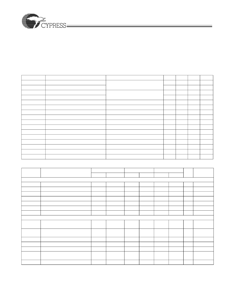
Maximum Ratings
[3]
Input Voltage Relative to V
SS
:.............................. V
SS
–
0.3V
Input Voltage Relative to V
DDQ
or AV
DD
: ............. V
DD
+ 0.3V
Storage Temperature: ................................
–
65
°
C to + 150
°
C
Operating Temperature:....................................0
°
C to +70
°
C
Maximum ESD.............................................................2000V
Maximum Power Supply: ................................................5.5V
DC Parameters
V
DD
= V
DDPCI
= V
DDAGP
= V
DDR
= V
DD48M
= V
DDC
= 3.3V ± 5%, V
DDI
= V
DD
= 2.5V ± 5%, T
A
= 0
°
C to +70
°
C
Parameter
Description
VIL1
Input Low Voltage
Applicable to PD#, F S(0:4)
VIH1
Input High Voltage
VIL2
Input Low Voltage
Applicable to SDATA and SCLK
VIH2
Input High Voltage
Vol
Output Low Voltage for SRESET#
Iol
Pull-down Current for SRESET#
Ioz
Three-state Leakage Current
Idd3.3V
Dynamic Supply Current
CPU Frequency Set at 133.3 MHz
[5]
Idd2.5V
Dynamic Supply Current
CPU Frequency Set at 133.3 MHz
[5]
Ipd
Power-down Supply Current
Ipup
Internal Pull-up Device Current
Ipdwn
Internal Pull-down Device Current
Cin
Input Pin Capacitance
Cout
Output Pin Capacitance
Lpin
Pin Inductance
Cxtal
Crystal Pin Capacitance
Measured from the X
IN
or X
OUT
to V
SS
AC Parameters
This device contains circuitry to protect inputs against damage
due to high-static voltages or electric field. However, precau-
tions should be take to avoid application of any voltage higher
than the maximum-rated voltages to this circuit. For proper
operation, V
IN
and V
OUT
should be constrained to the range:
V
SS
< (V
IN
or V
OUT
) < V
DD
.
Unused inputs must always be tied to an appropriate logic
voltage level (either V
SS
or V
DD
).
Conditions
Min.
Typ.
Max.
0.8
Unit
Vdc
Vdc
Vdc
Vdc
V
mA
μ
A
mA
mA
μ
A
μ
A
μ
A
pF
pF
pF
pF
2.0
1.0
2.2
0.4
24
I
OL
V
OL
= 0.4V
35
10
190
195
600
–
25
10
5
6
7
45
150
175
95
PD# = 0
Input @ V
SS
Input @ V
DD
27
36
Parameter
XTAL
TDC
TPeriod
VHIGH
VLOW
Tr/Tf
TCCJ
Txs
P4 Mode CPU at 0.7V
TDC
Description
100 MHz
Min.
133MHz
Min.
200 MHz
Min.
Unit
Notes
[4]
Max.
Max
Max
X
IN
Duty Cycle
X
IN
Period
X
IN
High Voltage
X
IN
Low Voltage
X
IN
Rise and Fall Times
X
IN
Cycle to Cycle Jitter
Crystal Start-up Time
45
55
71.0
V
DD
0.3V
DD
10.0
500
30
45
55
71.0
V
DD
0.3V
DD
10
500
30
45
55
71.0
V
DD
0.3V
DD
10
500
30
%
ns
V
V
ns
ps
ms
7,8
7,8
9
10
10
11,12
12,9
69.841
0.7V
DD
0
69.84
0.7V
DD
0
69.84
0.7V
DD
0
CPUT/C Duty Cycle
45
55
45
55
45
55
%
7,11,14,21,
22
7,11,14,21,
22
23,24
23,26,24
11,23,22
11,15,21,22
TPeriod
CPUT/C Period
9.85
10.2
7.35
7.65
4.85
5.1
ns
Tr/Tf
CPUT/C Rise and Fall Times
Rise/Fall Matching
Rise/Fall Time Variation
CPUCS_T/C to CPUT/C Clock
Skew
CPUT/C Cycle to Cycle Jitter
175
700
20%
125
200
175
700
20%
125
150
175
700
20%
125
200
ps
Delta Tr/Tf
TSKEW
ps
ps
0
0
0
TCCJ
Notes:
3.
4.
–
150
+150
–
150
+150
–
200
+200
ps
11,15,21,22
Multiple Supplies:
The Voltage on any input or I/O pin cannot exceed the power pin during power-up. Power supply sequencing is NOT required.
All notes for this table may be found at the end of the table, on page 12.
相關(guān)PDF資料 |
PDF描述 |
|---|---|
| CY28341OCT | Universal Single-Chip Clock Solution for VIA P4M266/KM266 DDR Systems |
| CY28341OC | Universal Single-Chip Clock Solution for VIA P4M266/KM266 DDR Systems |
| CY28346 | Clock Synthesizer with Differential CPU Outputs |
| CY28346OC | CONN BNC PLUG CRIMP RG-TFE-59,62 |
| CY28346OCT | CONN BNC PLUG CRIMP RG-59,62 |
相關(guān)代理商/技術(shù)參數(shù) |
參數(shù)描述 |
|---|---|
| CY28342 | 制造商:CYPRESS 制造商全稱:Cypress Semiconductor 功能描述:High-performance SiS645/650 Pentium 4 Clock Synthesizer |
| CY28342OC | 制造商:Rochester Electronics LLC 功能描述:- Bulk |
| CY28342OCT | 制造商:Rochester Electronics LLC 功能描述:- Tape and Reel |
| CY28342ZC | 制造商:CYPRESS 制造商全稱:Cypress Semiconductor 功能描述:High-performance SiS645/650 Pentium 4 Clock Synthesizer |
| CY28342ZCT | 制造商:CYPRESS 制造商全稱:Cypress Semiconductor 功能描述:High-performance SiS645/650 Pentium 4 Clock Synthesizer |
發(fā)布緊急采購(gòu),3分鐘左右您將得到回復(fù)。