- 您現(xiàn)在的位置:買賣IC網(wǎng) > PDF目錄384268 > CY26200 Clocks and Buffers PDF資料下載
參數(shù)資料
| 型號: | CY26200 |
| 英文描述: | Clocks and Buffers |
| 中文描述: | 時鐘和緩沖器 |
| 文件頁數(shù): | 2/5頁 |
| 文件大小: | 87K |
| 代理商: | CY26200 |
PRELIMINARY
CY26200
Document #: 38-07335 Rev. *A
Page 2 of 5
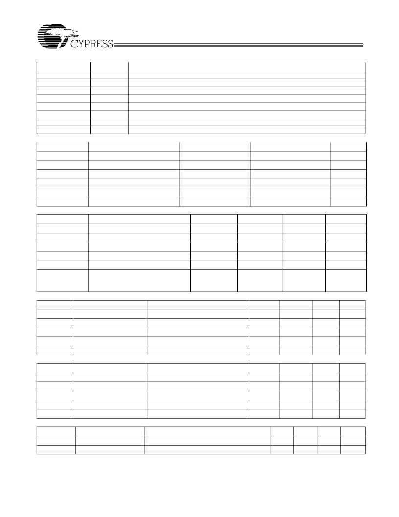
Pin Summary
Pin Name
Pin Number Pin Description
XIN
1
19.44-MHz Reference Input
AVDD
2
Analog Voltage Supply
FS
3
Frequency Select
–
see
Table 1
AVSS
4
Analog Ground
VDD
5
Voltage Supply
CLK1
6
1.544-MHz/2.048-MHz Clock Output
VSS
XOUT
[1]
Absolute Maximum Conditions
Parameter
V
DD
T
S
T
J
7
Ground
8
Reference Output
Description
Min.
–
0.5
–
65
Max.
7.0
125
125
V
DD
+ 0.3
V
DD
+ 0.3
Unit
V
°
C
°
C
V
V
V
Supply Voltage
Storage Temperature
[2]
Junction Temperature
Digital Inputs
Digital Outputs Referred to V
DD
Electrostatic Discharge
V
SS
–
0.3
V
SS
–
0.3
2000
Recommended Operating Conditions
Parameter
V
DD
/AV
DD
T
A
T
A
C
LOAD
f
REF
Description
Min.
3.135
0
–
40
Typ.
3.3
Max.
3.465
70
+85
15
Unit
V
°
C
°
C
pF
MHz
Operating Voltage
Ambient Temperature (Commercial)
Ambient Temperature (Industrial)
Max. Load Capacitance
Reference Frequency
Power-up time for all VDD's to reach
minimum specified voltage (power
ramps must be monotonic)
19.44
t
PU
0.05
500
ms
DC Electrical Characteristics
(Commercial)
Parameter
Description
I
OH
Output High Current
I
OL
Output Low Current
C
IN
Input Capacitance
I
IZ
Input Leakage Current
I
DD
Supply Current
DC Electrical Characteristics
(Industrial)
Parameter
Description
I
OH
Output High Current
I
OL
Output Low Current
C
IN
Input Capacitance
I
IZ
Input Leakage Current
I
DD
Supply Current
AC Electrical Characteristics
(V
DD
= 3.3V, Commercial)
Parameter
[3]
Description
DC
Output Duty Cycle
t
3
Rising Edge Slew Rate
Notes:
1.
Float XOUT if XIN is externally driven
2.
Rated for 10 years
3.
Not 100% tested
Conditions
Min.
12
12
Typ.
24
24
Max.
Unit
mA
mA
pF
μ
A
mA
V
OH
= V
DD
–
0.5, V
DD
= 3.3V
V
OL
= 0.5, V
DD
= 3.3V
7
5
Sum of Core and Output Current
20
Conditions
Min.
11
11
Typ.
24
Max.
Unit
mA
mA
pF
μ
A
mA
V
OH
= V
DD
–
0.5, V
DD
= 3.3V
V
OL
= 0.5, V
DD
= 3.3V
7
5
Sum of Core and Output Current
25
Conditions
Min.
45
0.8
Typ.
50
1.4
Max.
55
Unit
%
V/ns
Duty Cycle is defined in
Figure 1
, 50% of V
DD
Output Clock Rise Time, 20% - 80% of V
DD
相關(guān)PDF資料 |
PDF描述 |
|---|---|
| CY26210 | Clocks and Buffers |
| CY26211 | Clocks and Buffers |
| CY2DP3120 | Clocks and Buffers |
| CY2LL8422 | Clocks and Buffers |
| CY2LL843 | Clocks and Buffers |
相關(guān)代理商/技術(shù)參數(shù) |
參數(shù)描述 |
|---|---|
| CY26200_05 | 制造商:CYPRESS 制造商全稱:Cypress Semiconductor 功能描述:T1/E1 Clock Generator |
| CY26200SC | 制造商:Rochester Electronics LLC 功能描述:- Bulk |
| CY26200SCT | 制造商:Cypress Semiconductor 功能描述: |
| CY26200SI | 制造商:Rochester Electronics LLC 功能描述:- Bulk |
| CY26200SIT | 制造商:CYPRESS 制造商全稱:Cypress Semiconductor 功能描述:T1/E1 Clock Generator |
發(fā)布緊急采購,3分鐘左右您將得到回復(fù)。