- 您現(xiàn)在的位置:買賣IC網(wǎng) > PDF目錄379002 > CY22E016L-SZ35XIT (CYPRESS SEMICONDUCTOR CORP) 16-Kbit (2K x 8) nvSRAM PDF資料下載
參數(shù)資料
| 型號(hào): | CY22E016L-SZ35XIT |
| 廠商: | CYPRESS SEMICONDUCTOR CORP |
| 元件分類: | DRAM |
| 英文描述: | 16-Kbit (2K x 8) nvSRAM |
| 中文描述: | 2K X 8 NON-VOLATILE SRAM, 35 ns, PDSO28 |
| 封裝: | 0.300 INCH, ROHS COMPLIANT, MO-119, SOIC-28 |
| 文件頁數(shù): | 6/14頁 |
| 文件大小: | 748K |
| 代理商: | CY22E016L-SZ35XIT |
PRELIMINARY
CY22E016L
Document #: 001-06727 Rev. *C
Page 6 of 14
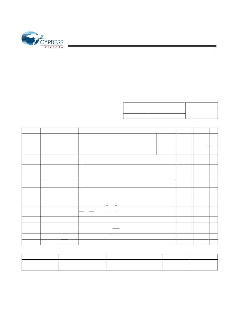
Maximum Ratings
(Above which the useful life may be impaired. For user guide-
lines, not tested.)
Storage Temperature .................................–65
°
C to +150
°
C
Ambient Temperature with
Power Applied.............................................–55
°
C to +125
°
C
Supply Voltage on V
CC
Relative to GND.......... –0.5V to 7.0V
Voltage Applied to Outputs
in High-Z State.......................................–0.5V to V
CC
+ 0.5V
Input Voltage............................................–0.5V to Vcc+0.5V
Transient Voltage (<20 ns) on
Any Pin to Ground Potential...................–0.5V to V
CC
+ 2.0V
Package Power Dissipation
Capability (T
A
= 25°C) ...................................................1.0W
Surface Mount Lead Soldering
Temperature (3 Seconds).......................................... +260
°
C
Output Short Circuit Current
[1]
....................................15 mA
Static Discharge Voltage.......................................... > 2001V
(per MIL-STD-883, Method 3015)
Latch-up Current.................................................... > 200 mA
Operating Range
Range
Ambient Temperature
0
°
C to +70
°
C
-40
°
C to +85
°
C
V
CC
Commercial
Industrial
4.5V to 5.5V
DC Electrical Characteristics
Over the Operating Range (V
CC
= 4.5V to 5.5V)
[2]
Parameter
I
CC1
Description
Average V
CC
Current
Test Conditions
Min.
Max.
85
75
65
75
Unit
mA
mA
mA
mA
t
RC
= 25 ns
t
RC
= 35 ns
t
RC
= 45 ns
Dependent on output loading and cycle rate.
Values obtained without output loads. I
OUT
= 0mA.
All Inputs Don’t Care, V
CC
= Max.
Average current for duration t
STORE
WE > (V
CC
– 0.2). All other inputs cycling.
Dependent on output loading and cycle rate. Values obtained
without output loads.
All Inputs Don’t Care, V
CC
= Max.
Average current for duration t
STORE
CE > (V
CC
– 0.2). All others V
IN
< 0.2V or > (V
CC
– 0.2V).
Standby current level after nonvolatile cycle is complete.
Inputs are static. f = 0MHz.
Input Leakage Current V
CC
= Max., V
SS
< V
IN
< V
CC
Off-State Output
Leakage Current
CE or OE > V
IH
Input HIGH Voltage
Input LOW Voltage
Output HIGH Voltage
I
OUT
= –4 mA except HSB
Output LOW Voltage
I
OUT
= 8 mA except HSB
Logic “0” on HSB
I
OUT
= 3 mA
Commercial
Industrial
I
CC2
Average V
CC
Current
during STORE
Average V
CC
Current at
t
AVAV
= 200 ns, 5V, 25°C
typical
Average V
CAP
Current
during AutoStore Cycle
V
CC
Standby Current
3
mA
I
CC3
10
mA
I
CC4
2
mA
I
SB
2.5
mA
I
ILK
I
OLK
-1
-5
+1
+5
μ
A
μ
A
V
CC
= Max., V
SS
< V
IN
< V
CC
,
V
IH
V
IL
V
OH
V
OL
V
BL
2.2
V
CC
+ 0.5
0.8
V
V
V
V
V
V
SS
– 0.5
2.4
0.4
0.4
Capacitance
[3]
Parameter
Description
Test Conditions
Max.
8
7
Unit
pF
pF
C
IN
C
OUT
Notes:
1. Outputs shorted for no more than one second. No more than one output shorted at a time.
2. Typical conditions for the Active Current shown on the front page of the data sheet are average values at 25°C (room temperature), and V
CC
= 5V. Not 100% tested.
3. These parameters are guaranteed but not tested.
Input Capacitance
Output Capacitance
T
A
= 25
°
C, f = 1 MHz,
V
CC
= 0 to 3.0 V
[+] Feedback
相關(guān)PDF資料 |
PDF描述 |
|---|---|
| CY22E016L-SZ45XCT | 16-Kbit (2K x 8) nvSRAM |
| CY2313ANZSC-1 | 13 Output, 3.3V SDRAM Buffer for Desktop PCs with 3 DIMMs |
| CY2412 | MPEG Clock Generator with VCXO |
| CY2412SC-1 | MPEG Clock Generator with VCXO |
| CY2412SC-1T | MPEG Clock Generator with VCXO |
相關(guān)代理商/技術(shù)參數(shù) |
參數(shù)描述 |
|---|---|
| CY22E016L-SZ45XC | 功能描述:NVRAM nvSRAM 2Kx8 5V COM RoHS:否 制造商:Maxim Integrated 數(shù)據(jù)總線寬度:8 bit 存儲(chǔ)容量:1024 Kbit 組織:128 K x 8 接口類型:Parallel 訪問時(shí)間:70 ns 電源電壓-最大:5.5 V 電源電壓-最小:4.5 V 工作電流:85 mA 最大工作溫度:+ 70 C 最小工作溫度:0 C 封裝 / 箱體:EDIP 封裝:Tube |
| CY22E016L-SZ45XCT | 制造商:CYPRESS 制造商全稱:Cypress Semiconductor 功能描述:16 Kbit (2K x 8) nvSRAM |
| CY22E016L-SZ45XI | 功能描述:NVRAM nvSRAM 2Kx8 5V IND RoHS:否 制造商:Maxim Integrated 數(shù)據(jù)總線寬度:8 bit 存儲(chǔ)容量:1024 Kbit 組織:128 K x 8 接口類型:Parallel 訪問時(shí)間:70 ns 電源電壓-最大:5.5 V 電源電壓-最小:4.5 V 工作電流:85 mA 最大工作溫度:+ 70 C 最小工作溫度:0 C 封裝 / 箱體:EDIP 封裝:Tube |
| CY22E016L-SZ45XIT | 制造商:CYPRESS 制造商全稱:Cypress Semiconductor 功能描述:16 Kbit (2K x 8) nvSRAM |
| CY22J | 制造商:SUNX 功能描述:New |
發(fā)布緊急采購(gòu),3分鐘左右您將得到回復(fù)。