- 您現(xiàn)在的位置:買賣IC網(wǎng) > PDF目錄378950 > CSR2930800BA (Electronic Theatre Controls, Inc.) FLASH MEMORY CMOS 8M (1M x 8/512K x 16) BIT PDF資料下載
參數(shù)資料
| 型號: | CSR2930800BA |
| 廠商: | Electronic Theatre Controls, Inc. |
| 英文描述: | FLASH MEMORY CMOS 8M (1M x 8/512K x 16) BIT |
| 中文描述: | 閃存的CMOS 800萬(100萬x 8/512K × 16)位 |
| 文件頁數(shù): | 20/50頁 |
| 文件大?。?/td> | 475K |
| 代理商: | CSR2930800BA |
第1頁第2頁第3頁第4頁第5頁第6頁第7頁第8頁第9頁第10頁第11頁第12頁第13頁第14頁第15頁第16頁第17頁第18頁第19頁當前第20頁第21頁第22頁第23頁第24頁第25頁第26頁第27頁第28頁第29頁第30頁第31頁第32頁第33頁第34頁第35頁第36頁第37頁第38頁第39頁第40頁第41頁第42頁第43頁第44頁第45頁第46頁第47頁第48頁第49頁第50頁
CSR2930800BA
-90
20
7.
Extended Command
(1) Fast Mode
CSR2930800BA has Fast Mode function. This mode dispenses with the initial two unclock cycles required in
the standard program command sequence by writing Fast Mode command into the command register. In this
mode, the required bus cycle for programming is two cycles instead of four bus cycles in standard program
command. (Do not write erase command in this mode.) The read operation is also executed after exiting this
mode. To exit this mode, it is necessary to write Fast Mode Reset command into the command register. (Refer
to “8. Embedded Program
TM
Algorithm for Fast Mode” in “
I
FLOW CHART” Extended algorithm.) The V
CC
active
current is required even CE = V
IH
during Fast Mode.
(2) Fast Programming
During Fast Mode, the programming can be executed with two bus cycles operation. The Embedded Program
Algorithm is executed by writing program set-up command (A0h) and data write cycles (PA/PD). (Refer to “8.
Embedded Program
TM
Algorithm for Fast Mode” in “
I
FLOW CHART” Extended algorithm.)
(3) Extended Sector Protection
In addition to normal sector protection, the CSR2930800BA has Extended Sector Protection as extended func-
tion. This function enable to protect sector by forcing V
ID
on RESET pin and write a commnad sequence. Unlike
conventional procedure, it is not necessary to force V
ID
and control timing for control pins. The only RESET pin
requires V
ID
for sector protection in this mode. The extended sector protect requires V
ID
on RESET pin. With this
condition, the operation is initiated by writing the set-up command (60h) into the command register. Then, the
sector addresses pins (A
18
, A
17
, A
16
, A
15
, A
14
, A
13
and A
12
) and (A
6
, A
1
, A
0
) = (0, 1, 0) should be set to the sector
to be protected (recommend to set V
IL
for the other addresses pins), and write extended sector protect command
(60h). A sector is typically protected in 150
μ
s. To verify programming of the protection circuitry, the sector
addresses pins (A
18
, A
17
, A
16
, A
15
, A
14
, A
13
and A
12
) and (A
6
, A
1
, A
0
) = (0, 1, 0) should be set and write a command
(40h). Following the command write, a logical “1” at device output DQ
0
will produce for protected sector in the
read operation. If the output data is logical “0”, please repeat to write extended sector protect command (60h)
again. To terminate the operation, it is necessary to set RESET pin to V
IH
.
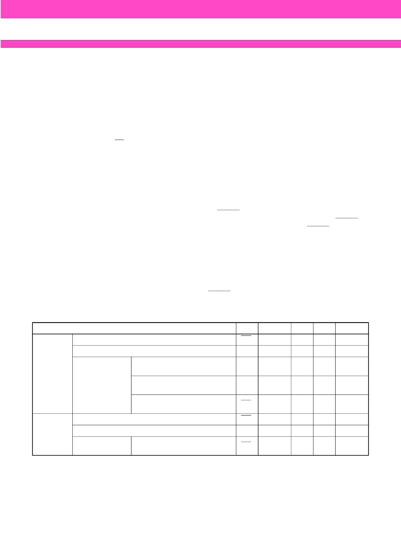
Write Operation Status
Hardware Sequence Flags Table
8.
*1:Performing successive read operations from any address will cause DQ
6
to toggle.
*2:Reading the byte address being programmed while in the erase-suspend program mode will indicate logic “1”
at the DQ
2
bit. However, successive reads from the erase-suspended sector will cause DQ
2
to toggle.
Notes:
DQ
0
and DQ
1
are reserve pins for future use.
DQ
4
is internal use only.
Status
DQ
7
DQ
6
DQ
5
DQ
3
DQ
2
In Progress
Embedded Program Algorithm
DQ
7
Toggle
0
0
1
Embedded Erase Algorithm
0
Toggle
0
1
Toggle
Erase
Suspended Mode
Erase Suspend Read
(Erase Suspended Sector)
1
1
0
0
Toggle
Erase Suspend Read
(Non-Erase Suspended Sector)
Data
Data
Data
Data
Data
Erase Suspend Program
(Non-Erase Suspended Sector)
DQ
7
Toggle *
1
0
0
1 *
2
Exceeded
Time Limits
Embedded Program Algorithm
DQ
7
Toggle
1
0
1
Embedded Erase Algorithm
0
Toggle
1
1
N/A
Erase
Suspended Mode
Erase Suspend Program
(Non-Erase Suspended Sector)
DQ
7
Toggle
1
0
N/A
相關(guān)PDF資料 |
PDF描述 |
|---|---|
| CSR772 | CSR Reverse Conducting Thyristors |
| CSR148 | CSR Reverse Conducting Thyristors |
| CSR148-11 | CSR Reverse Conducting Thyristors |
| CSR149 | CSR Reverse Conducting Thyristors |
| CSR772-22 | CSR Reverse Conducting Thyristors |
相關(guān)代理商/技術(shù)參數(shù) |
參數(shù)描述 |
|---|---|
| CSR-2SV-BLK | 制造商:JBL Commercial 功能描述:Remote Wall Volume Control for CSM Mixer Black 制造商:JBL COMMERCIAL 功能描述:REMOTE WALL VOLUME CONTROL FOR CSM MIXER BLACK |
| CSR-2SV-WHT | 制造商:JBL Commercial 功能描述:Remote Wall Volume Control for CSM Mixer White 制造商:JBL COMMERCIAL 功能描述:REMOTE WALL VOLUME CONTROL FOR CSM MIXER WHITE |
| CSR2TB | 制造商:CAMDENBOSS 功能描述:STRAIN RELIEF 3WAY TERMINAL BLOCK |
| CSR2TTE10L0D | 制造商:KOA 制造商全稱:KOA Speer Electronics, Inc. 功能描述:four-terminal current sense resistor |
| CSR2TTE10L0F | 制造商:KOA 制造商全稱:KOA Speer Electronics, Inc. 功能描述:four-terminal current sense resistor |
發(fā)布緊急采購,3分鐘左右您將得到回復。