- 您現(xiàn)在的位置:買賣IC網(wǎng) > PDF目錄4068 > CS80C286-16 (Intersil)IC CPU 16BIT 5V 16MHZ 68-PLCC PDF資料下載
參數(shù)資料
| 型號: | CS80C286-16 |
| 廠商: | Intersil |
| 文件頁數(shù): | 58/60頁 |
| 文件大小: | 0K |
| 描述: | IC CPU 16BIT 5V 16MHZ 68-PLCC |
| 標準包裝: | 126 |
| 處理器類型: | 80C286 16-位 |
| 速度: | 16MHz |
| 電壓: | 5V |
| 安裝類型: | 表面貼裝 |
| 封裝/外殼: | 68-LCC(J 形引線) |
| 供應商設備封裝: | 68-PLCC(24.23x24.23) |
| 包裝: | 管件 |
第1頁第2頁第3頁第4頁第5頁第6頁第7頁第8頁第9頁第10頁第11頁第12頁第13頁第14頁第15頁第16頁第17頁第18頁第19頁第20頁第21頁第22頁第23頁第24頁第25頁第26頁第27頁第28頁第29頁第30頁第31頁第32頁第33頁第34頁第35頁第36頁第37頁第38頁第39頁第40頁第41頁第42頁第43頁第44頁第45頁第46頁第47頁第48頁第49頁第50頁第51頁第52頁第53頁第54頁第55頁第56頁第57頁當前第58頁第59頁第60頁

7
The 80C286 can be single-stepped using only the CPU
clock. This state can be maintained as long as necessary.
Single step clock information allows simple interface circuitry
to provide critical information for system debug.
Static design also allows very low frequency operation
(down to DC). In a power critical situation, this can provide
low power operation since 80C286 power dissipation is
directly related to operating frequency. As the system fre-
quency is reduced, so is the operating power until, ulti-
mately, with the clock stopped in phase two of the processor
clock cycle, the 80C286 power requirement is the standby
current (5mA maximum).
80C286 Base Architecture
The 80C86, 80C88, and 80C286 CPU family all contain the
same basic set of registers, instructions, and addressing
modes. The 80C286 processor is upwardly compatible with
the 80C86 and 80C88 CPU's.
Register Set
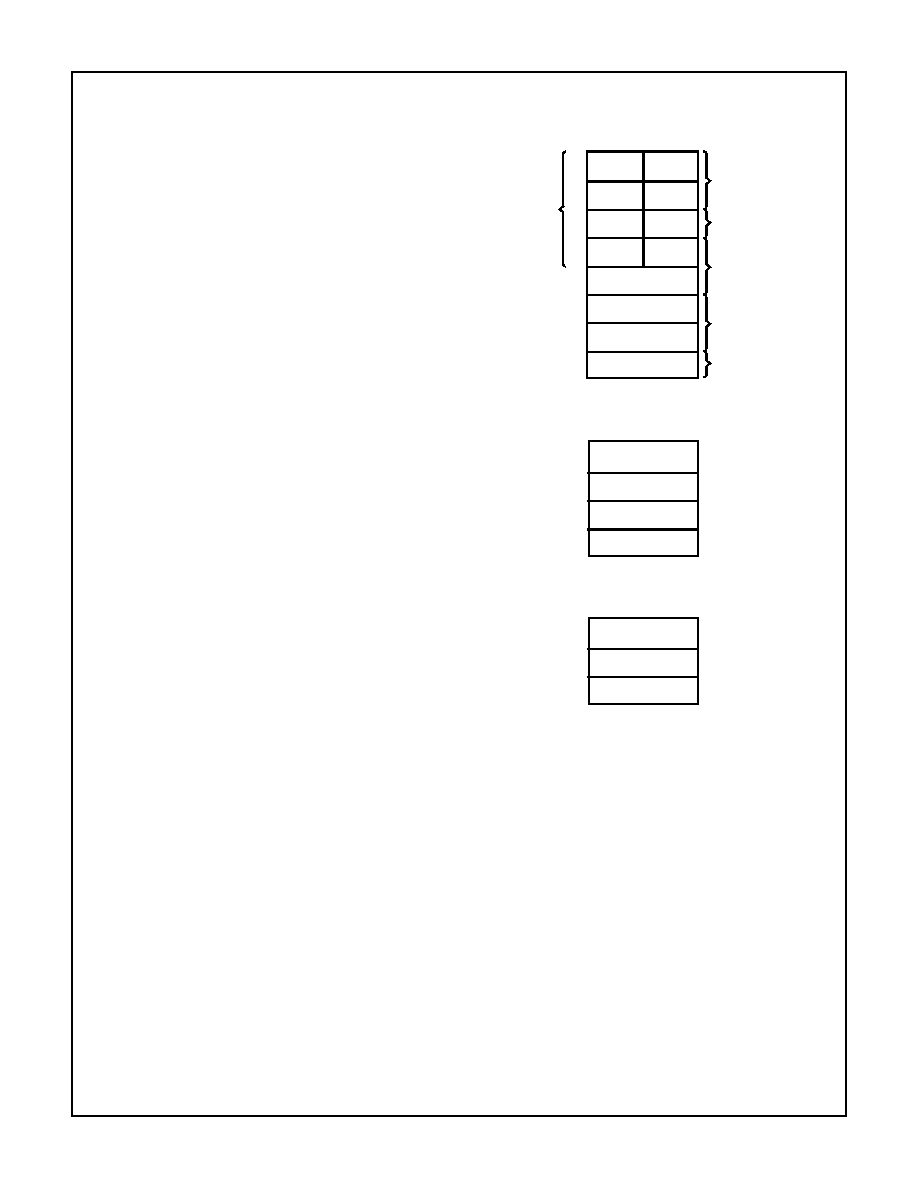
The 80C286 base architecture has fifteen registers as
shown in Figure 1. These registers are grouped into the fol-
lowing four categories.
GENERAL REGISTERS: Eight 16-bit general purpose regis-
ters used to contain arithmetic and logical operands. Four of
these (AX, BX, CX and DX) can be used either in their
entirety as 16-bit words or split into pairs of separate 8-bit
registers.
SEGMENT REGISTERS: Four 16-bit special purpose regis-
ters select, at any given time, the segments of memory that
are immediately addressable for code, stack and data. (For
usage, refer to Memory Organization.)
BASE AND INDEX REGISTERS: Four of the general pur-
pose registers may also be used to determine offset
addresses of operands in memory. These registers may
contain base addresses or indexes to particular locations
within a segment. The addressing mode determines the spe-
cific registers used for operand address calculations.
STATUS AND CONTROL REGISTERS: Three 16-bit spe-
cial purpose registers record or control certain aspects of the
80C286 processor state. These include the Flags register
and Machine Status Word register shown in Figure 2, and
the Instruction Pointer, which contains the offset address of
the next sequential instruction to be executed.
Flags Word Description
The Flags word (Flags) records specific characteristics of
the result of logical and arithmetic instructions (bits 0, 2, 4, 6,
7 and 11) and controls the operation of the 80C286 within a
given operating mode (bits 8 and 9). Flags is a 16-bit regis-
ter. The function of the flag bits is given in Table 1.
AH
AL
DL
CL
BL
DH
CH
BH
AX
DX
CX
BX
BP
SI
DI
SP
BYTE
ADDRESSABLE
(8-BIT
REGISTER
NAMES
SHOWN)
MULTIPLY/DIVIDE
I/O INSTRUCTIONS
LOOP/SHIFT/REPEAT
BASE REGISTERS
COUNT
INDEX REGISTERS
STACK POINTER
15
0
7
0
7
SPECIAL
REGISTER
FUNCTIONS
16-BIT
REGISTER
NAME
GENERAL
REGISTERS
CS
DS
SS
ES
0
15
CODE SEGMENT
SEGMENT
REGISTERS
SELECTOR
DATA SEGMENT
SELECTOR
STACK SEGMENT
SELECTOR
EXTRA SEGMENT
SELECTOR
F
0
15
FLAGS
INSTRUCTION
MACHINE
POINTER
STATUS WORD
IP
MSW
STATUS AND CONTROL
REGISTERS
FIGURE 1. REGISTER SET
80C286
相關PDF資料 |
PDF描述 |
|---|---|
| ACB90DHAR | CONN EDGECARD 180PS R/A .050 DIP |
| MPC857TZQ66B | IC MPU PWRQUICC 66MHZ 357-PBGA |
| ABB95DHAS | CONN EDGECARD 190PS R/A .050 SLD |
| MPC857TVR66B | IC MPU POWERQUICC 66MHZ 357-PBGA |
| MPC8271ZQTIEA | IC MPU POWERQUICC II 516-PBGA |
相關代理商/技術參數(shù) |
參數(shù)描述 |
|---|---|
| CS80C286-1696 | 制造商:Rochester Electronics LLC 功能描述:- Bulk |
| CS80C286-2 | 制造商:Harris Corporation 功能描述: |
| CS80C286-20 | 制造商:Rochester Electronics LLC 功能描述:- Bulk |
| CS80C286-2096 | 制造商:Rochester Electronics LLC 功能描述:- Bulk |
| CS80C286-20S2463 | 制造商:Rochester Electronics LLC 功能描述:- Bulk |
發(fā)布緊急采購,3分鐘左右您將得到回復。