- 您現(xiàn)在的位置:買賣IC網(wǎng) > PDF目錄379689 > ASC7611QS24 (Electronic Theatre Controls, Inc.) HARDWARE MONITOR WITH INTEGRATED FAN CONTROL PDF資料下載
參數(shù)資料
| 型號(hào): | ASC7611QS24 |
| 廠商: | Electronic Theatre Controls, Inc. |
| 英文描述: | HARDWARE MONITOR WITH INTEGRATED FAN CONTROL |
| 中文描述: | 五金顯示器整合了風(fēng)扇控制 |
| 文件頁數(shù): | 18/40頁 |
| 文件大小: | 505K |
| 代理商: | ASC7611QS24 |
第1頁第2頁第3頁第4頁第5頁第6頁第7頁第8頁第9頁第10頁第11頁第12頁第13頁第14頁第15頁第16頁第17頁當(dāng)前第18頁第19頁第20頁第21頁第22頁第23頁第24頁第25頁第26頁第27頁第28頁第29頁第30頁第31頁第32頁第33頁第34頁第35頁第36頁第37頁第38頁第39頁第40頁

P
P
- 18 -
Andigilog, Inc. 2006
www.andigilog.com
October 2006 - 70A05007
aSC7611
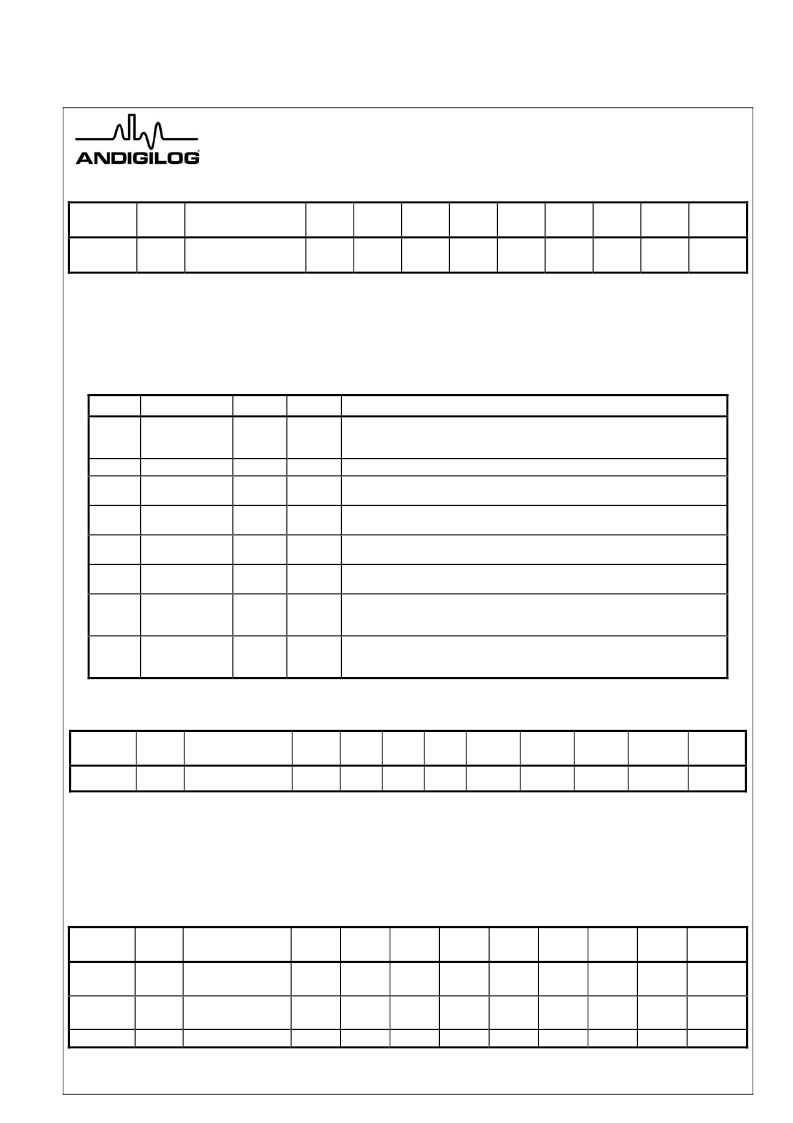
Register 42h: Interrupt Status Register 2
Register
Address
Read/
Write
Register Name
Bit 7
(MSB)
Bit 6
Bit 5
Bit 4
Bit 3
Bit 2
Bit 1
Bit 0
(LSB)
Default
Value
42h
R
Interrupt Status 2
ERR2
ERR1
FAN4
FAN3
FAN2
FAN1
RES
12V
00
The Interrupt Status Register 2 bits will be automatically set, by the aSC7611, whenever a fault condition is detected.
Interrupt Status Register 2 identifies faults caused by temperature sensor error, fan speed dropping below minimum set by
the tachometer minimum register. Interrupt Status Register 2 will hold a set bit until the event is read by software. The
contents of this register will be cleared (set to 0) automatically by the aSC7611 after it is read by software, if fault condition
no longer exists. Once set, the Interrupt Status Register 2 bits will remain set until a read event occurs, even if the fault no
longer exists. This register is read-only – a write to this register has no effect.
Bit
Name
R/W
Default
Description
0
12V Limits
Exceeded
R
0
The aSC7611 automatically sets this bit to 1 when the 12V input voltage is
less than or equal to the limit set in the 12V Low Limit register or greater than
the limit set in the 12V High Limit register.
1
RES
R
0
Reserved
2
FAN 1
STALLED
R
0
The aSC7611 automatically sets this bit to 1 when the TACH 1 input reading is
above the count value set in the Tach 1 Minimum MSB and LSB registers.
3
FAN 2
STALLED
R
0
The aSC7611 automatically sets this bit to 1 when the TACH 2 input reading is
above the count value set in the Tach 2 Minimum MSB and LSB registers.
4
FAN 3
STALLED
R
0
The aSC7611 automatically sets this bit to 1 when the TACH 3 input reading is
above the count value set in the Tach 3 Minimum MSB and LSB registers.
5
FAN 4
STALLED
R
0
The aSC7611 automatically sets this bit to 1 when the TACH 4 input reading is
above the count value set in the Tach 4 Minimum MSB and LSB registers.
The aSC7611 automatically sets this bit to 1 when there is an open circuit fault
on the Remote1+ or Remote1- thermal diode input pins. A diode fault will also
set bit 4 Zone 1 Limit bit, of Interrupt Status Register 1.
6
Remote Diode
1 Fault
R
0
7
Remote Diode
2 Fault
R
0
The aSC7611 automatically sets this bit to 1 when there is an open circuit fault
on the Remote2+ or Remote2- thermal diode input pins. A diode fault will also
set bit 6 Zone 3 Limit bit, of Interrupt Status Register 1.
Table 5 Interrupt Status Register 2
Register 43h: VID Register
Register
Address
Read/
Write
Register Name
Bit 7
(MSB)
Bit 6
Bit 5
Bit 4
Bit 3
Bit 2
Bit 1
Bit 0
(LSB)
Default
Value
43h
R
VID0-4
RES
RES
RES
VID4
VID3
VID2
VID1
VID0
00
The VID register contains the values of aSC7611 VID0–VID4 input pins. This register indicates the status of the VID lines
that interconnect the processor to the Voltage Regulator Module (VRM). Software uses the information in this register to
determine the voltage that the processor is designed to operate at. With this information, software can then dynamically
determine the correct values to place in the VCCP Low Limit and VCCP High Limit registers. This register is read-only – a
write to this register has no effect.
Tachometer Measurement and Configuration
Register 28-2Fh: Fan Tachometer Reading
Register
Address
Read/
Write
Register Name
Bit 7
(MSB)
Bit 6
Bit 5
Bit 4
Bit 3
Bit 2
Bit 1
Bit 0
(LSB)
Default
Value
28h
29h
R
R
Tach 1 LS Byte
Tach 1 MS Byte
7
15
6
14
5
13
4
12
3
11
2
10
1
9
0
8
N/A
N/A
2Ah
2Bh
R
R
Tach 2 LS Byte
Tach 2 MS Byte
7
15
6
14
5
13
4
12
3
11
2
10
1
9
0
8
N/A
N/A
2Ch
R
Tach 3 LS Byte
7
6
5
4
3
2
1
0
N/A
相關(guān)PDF資料 |
PDF描述 |
|---|---|
| ASC7621 | HARDWARE MONITOR WITH INTEGRATED FAN CONTROL |
| ASC7621QS24 | HARDWARE MONITOR WITH INTEGRATED FAN CONTROL |
| ASD05H-12S5 | Isolated and Regulated 5 WATT Open Frame DC/DC Converter |
| ASD05H-12S9 | Isolated and Regulated 5 WATT Open Frame DC/DC Converter |
| ASD05H-48D12 | Isolated and Regulated 5 WATT Open Frame DC/DC Converter |
相關(guān)代理商/技術(shù)參數(shù) |
參數(shù)描述 |
|---|---|
| ASC7621 | 制造商:未知廠家 制造商全稱:未知廠家 功能描述:HARDWARE MONITOR WITH INTEGRATED FAN CONTROL |
| ASC7621QS24 | 制造商:未知廠家 制造商全稱:未知廠家 功能描述:HARDWARE MONITOR WITH INTEGRATED FAN CONTROL |
| ASC-8-2-CB (5-PIN) | 制造商:Belden Inc 功能描述:ASC-8-2-CB (5-PIN) |
| ASC-8-2-LED PUR 10M(5-CONTACT) | 制造商:Belden Inc 功能描述:ASC-8-2-LED PUR 10M(5-CONTACT) |
| ASC8848AETE | 制造商:NXP Semiconductors 功能描述:IC VIDEO PROCESSOR ADV 484TFBGA 制造商:NXP Semiconductors 功能描述:ASC8848AET/TFBGA/TRAYBDP// |
發(fā)布緊急采購,3分鐘左右您將得到回復(fù)。