- 您現(xiàn)在的位置:買賣IC網(wǎng) > PDF目錄378405 > AND8054 (ON SEMICONDUCTOR) Designing RC Oscillator Circuits with Low Voltage Operational Amplifiers and Comparators for Precision Sensor Applications PDF資料下載
參數(shù)資料
| 型號: | AND8054 |
| 廠商: | ON SEMICONDUCTOR |
| 英文描述: | Designing RC Oscillator Circuits with Low Voltage Operational Amplifiers and Comparators for Precision Sensor Applications |
| 中文描述: | RC振蕩器電路設(shè)計低電壓運算放大器和精密傳感器應(yīng)用比較 |
| 文件頁數(shù): | 4/28頁 |
| 文件大小: | 168K |
| 代理商: | AND8054 |
第1頁第2頁第3頁當前第4頁第5頁第6頁第7頁第8頁第9頁第10頁第11頁第12頁第13頁第14頁第15頁第16頁第17頁第18頁第19頁第20頁第21頁第22頁第23頁第24頁第25頁第26頁第27頁第28頁
AND8054/D
http://onsemi.com
4
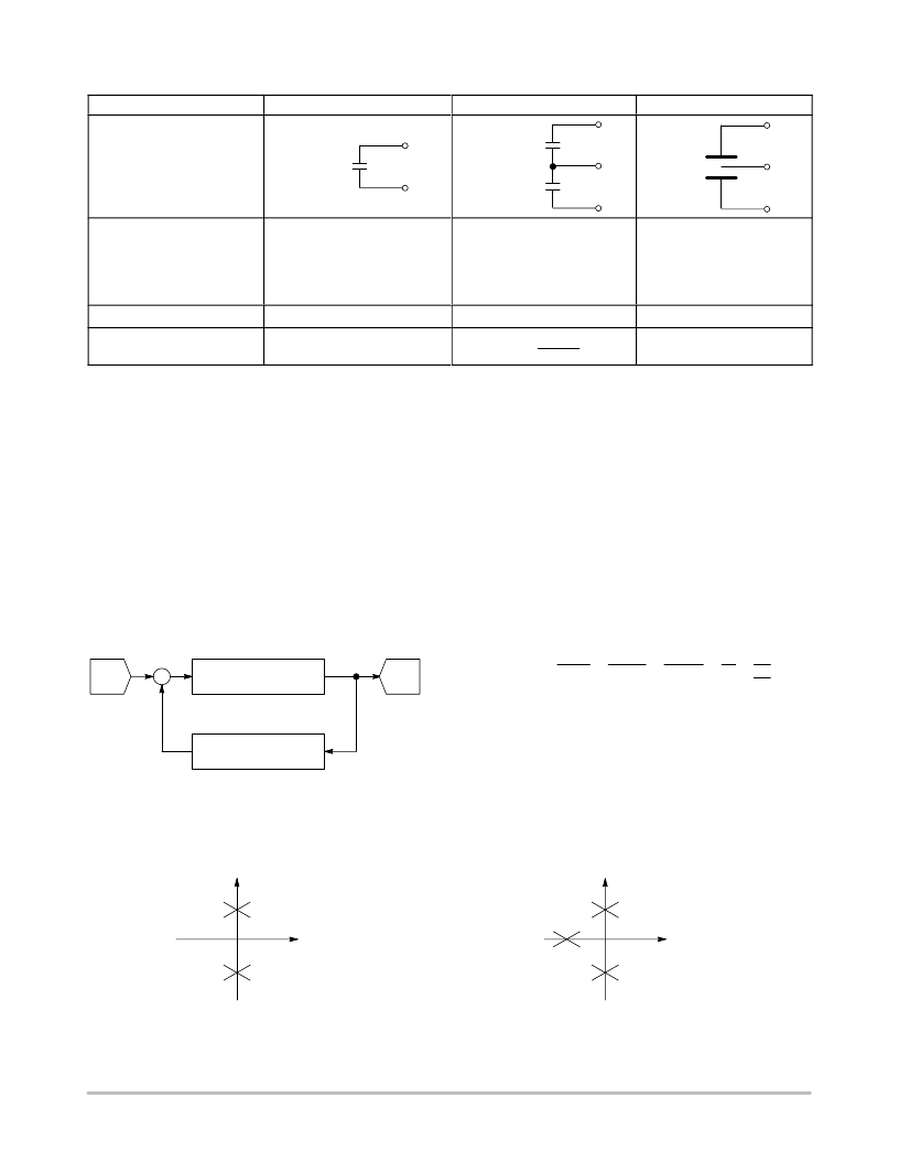
Table 1. Summary of Capacitive Sensors
áááááááááááááááááááááááááááááá
á
á
á
áááááááááááááááááááááááááááááá
á
á
á
ááááááááááááááááááááááááááááááá
á
áááááááááááááááááááááááá
Sensor Configuration
áááááááááááááááááááááááááááááá
ááááááá
ááááááá
ááááááá
ááááááá
ááááááá
ááááááá
á
á
á
á
Absolute
CMEAS
Dual
á
á
áááááááá
á
á
áááááááá
áááááááá
Differential
á
áááááááá
áááááááá
áááááááá
Schematic Representation
áááááááá
áááááááá
áááááááá
Acceleration
Oil Level
CMEAS
áááááááá
áááááááá
áááááááá
áááááááá
áááááááá
áááááááá
freq.
á
áááááá
CREF
áááááá
áááááá
áááááá
á
á
á
á
á
Absolute Pressure
á
á
á
á
Displacement
Proximity
áááááááááááááááááááááááááááááá
ááááááá
á
áááááááá
áááááááá
á
áááááá
á
OSCILLATOR THEORY
An oscillator is a positive feedback control system which
does not have an external input signal, but will generate an
output signal if certain conditions are met. In practice, a small
input is applied to the feedback system from factors such as
noise pick–up or power supply transients, and this initiates the
feedback process to produce a sustained oscillation. A block
diagram of an oscillator is shown in Figure 3.
The poles of the denominator of the transfer equation T(s),
or equivalently the zeroes of the characteristic equation,
determine the time domain behavior of the system. If T(s)
has all of its poles located within the left plane, the system
is stable because the corresponding terms are all
exponentially decaying. In contrast, if T(s) has one pole that
lies within the right half plane, the system is unstable
because the corresponding term exponentially increases in
amplitude. An oscillator is on the borderline between a
stable and an unstable system and is formed when a pair of
poles is on the imaginary axis, as shown in Figure 4.
If the magnitude of the loop gain is greater than one and
the phase is zero, the amplitude of oscillation will increase
exponentially until a factor in the system such as the supply
voltage restricts the growth. In contrast, if the magnitude of
the loop gain is less than one, the amplitude of oscillation
will exponentially decrease to zero.
A
≡
Amplifier Gain
≡
Feedback Factor
+
–
Figure 3. Block Diagram of an Oscillator
V
OUT
V
IN
T(s)
VOUT
VIN
A
1
A
A
1
LG
A
s
A
N(s)
D(s)
where
A
LG
loop gain
s
characteristic equation
If VIN
0, then T(s)
when
s
0
|LG|
1 (magnitude) and
LG
0 (phase).
At the oscillation condition of s = 0, referred
to as the Barkhausen stability
criterion,
Imaginary (j
ω
)
Imaginary (j
ω
)
Real (
ω
)
Real (
ω
)
2nd Order Oscillator
3rd Order Oscillator
Figure 4. Pole Locations for a 2nd and 3rd Order Oscillator
相關(guān)PDF資料 |
PDF描述 |
|---|---|
| AND8058 | Two New Analog Switches Set Standards for Space Efficiency |
| AND8058D | Two New Analog Switches Set Standards for Space Efficiency |
| AND8066 | Interfacing with ECLinPS |
| AND8066D | Interfacing with ECLinPS |
| AND8067 | NL27WZ04 Dual Gate Inverter Oscillator Increases the Brightness of LEDs While Reducing Power Consumption |
相關(guān)代理商/技術(shù)參數(shù) |
參數(shù)描述 |
|---|---|
| AND8058 | 制造商:ONSEMI 制造商全稱:ON Semiconductor 功能描述:Two New Analog Switches Set Standards for Space Efficiency |
| AND8058D | 制造商:ONSEMI 制造商全稱:ON Semiconductor 功能描述:Two New Analog Switches Set Standards for Space Efficiency |
| AND8066 | 制造商:ONSEMI 制造商全稱:ON Semiconductor 功能描述:Interfacing with ECLinPS |
| AND8066D | 制造商:ONSEMI 制造商全稱:ON Semiconductor 功能描述:Interfacing with ECLinPS |
| AND8067 | 制造商:ONSEMI 制造商全稱:ON Semiconductor 功能描述:NL27WZ04 Dual Gate Inverter Oscillator Increases the Brightness of LEDs While Reducing Power Consumption |
發(fā)布緊急采購,3分鐘左右您將得到回復(fù)。