- 您現(xiàn)在的位置:買賣IC網(wǎng) > PDF目錄378403 > AN1504D (ON SEMICONDUCTOR) Metastability and the ECLinPS Family PDF資料下載
參數(shù)資料
| 型號: | AN1504D |
| 廠商: | ON SEMICONDUCTOR |
| 英文描述: | Metastability and the ECLinPS Family |
| 中文描述: | 亞穩(wěn)態(tài)和業(yè)界的EClinPS家庭 |
| 文件頁數(shù): | 1/8頁 |
| 文件大小: | 135K |
| 代理商: | AN1504D |
Semiconductor Components Industries, LLC, 2004
November, 2004
Rev. 2
1
Publication Order Number:
AN1504/D
AN1504/D
Metastability and the
ECLinPS
Family
Prepared by: Applications Engineering
This application note examines the concept of
metastability and provides a theoretical discussion of how it
occurs, including examples of the metastable condition. An
equation characterizing metastability and a test circuit
derived from that equation are presented. Metastability
results are then applied to the ECLinPS family.
Introduction
Metastability is a central issue anytime a designer wishes
to synchronize two or more asynchronous signals. A popular
method for accomplishing this task is to employ a D
flip
flop as the synchronizing element (Figure 1).
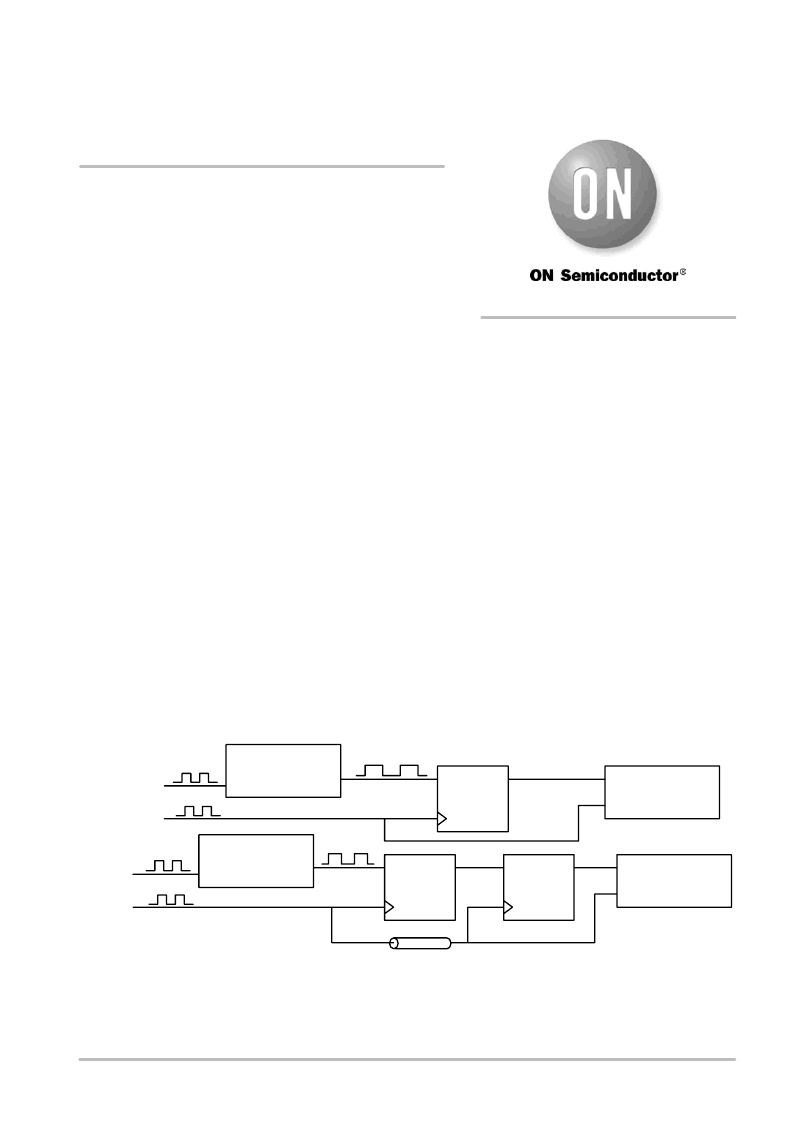
As shown in Figure 1, synchronization can be
accomplished using a single D flip
flop; more typically,
several D flip
flops are cascaded to provide synchronization
while reducing the probability of a metastable or
“anomalous” state occurring at the input of System 2.
Unfortunately the information at the data and clock inputs of
flip
flops used as synchronizing elements is asynchronous by
nature, thus the manufacturer specifications for set
up and
hold times may not be observed. A series of timing diagrams
is shown in Figure 2 demonstrating three possible timing
relationships between the data and clock signals; to the right
of each data trace is the corresponding output waveform. In
the first case the data adheres to the specified set
up and hold
times, hence the output attains the proper state. In case 2 the
set
up time is violated such that the output of the D flip
flop
does not change state. Case 3 represents a violation of the
set
up and hold times whereby the D flip
flop enters a
metastable state. The resolving time for a flip
flop in this
metastable state is indeterminate. Further, the final settling
state of the flip
flop having been in this metastable condition
cannot be guaranteed.
Metastability Theory
A bistable device such as a flip
flop has two stable output
states: the “1” or high state and the “0” or low state. When
the manufacturers specified set
up and hold times are
observed the flip
flop will achieve the proper output state
(Figure 3). However if the set
up and hold times are
violated the device may enter a metastable state, thereby
increasing the propagation delay, as indicated by the output
response shown in Figure 4.
To better understand flip
flop metastability, the operation
of a typical ECLinPS D flip
flop is reviewed. The schematic
of a D flip
flop is shown in Figure 5.
SYSTEM 2 INPUT
SYSTEM 2
Q
CLOCK
DATA
D FLIPFLOP
SYSTEM 2
CLOCK
SYSTEM 1
OUTPUT
SYSTEM 1
CLOCK
SYSTEM 1
T
D
DELAY
SYSTEM 2 INPUT
SYSTEM 2
SYSTEM 2
CLOCK
SYSTEM 1
OUTPUT
SYSTEM 1
CLOCK
SYSTEM 1
Q
CLOCK
DATA
D FLIPFLOP
Q
CLOCK
DATA
D FLIPFLOP
Figure 1. Clock Synchronization Schemes
APPLICATION NOTE
http://onsemi.com
相關PDF資料 |
PDF描述 |
|---|---|
| AN1568 | Interfacing Between LVDS and ECL |
| AN1568D | Interfacing Between LVDS and ECL |
| AN1593 | LOW COST 1.0 A CURRENT SOURCE FOR BATTERY CHARGERS |
| AN1607 | ITC122 low voltage micro to motor interface |
| AN1672 | The ECL Translator Guide |
相關代理商/技術參數(shù) |
參數(shù)描述 |
|---|---|
| AN15167A-VT | 制造商:Panasonic Industrial Company 功能描述:IC |
| AN1523 | 制造商:STMICROELECTRONICS 制造商全稱:STMicroelectronics 功能描述:11W FLYBACK CONVERTER FOR AUXILIARY POWER SUPPLY APPLICATION USING THE L6590 |
| AN1527 | 制造商:STMICROELECTRONICS 制造商全稱:STMicroelectronics 功能描述:DEVELOPING A USB SMARTCARD READER WITH ST7SCR |
| AN1549.0 | 制造商:INTERSIL 制造商全稱:Intersil Corporation 功能描述:Addressing Power Issues in Real Time Clock Applications |
| AN155 | 制造商:SILABS 制造商全稱:SILABS 功能描述:STEPPER MOTOR REFERENCE DESIGN |
發(fā)布緊急采購,3分鐘左右您將得到回復。