- 您現(xiàn)在的位置:買賣IC網(wǎng) > PDF目錄378403 > AN1082 (Intersil Corporation) Using the ISL6401 RSLIC PWM Controller Evaluation Board PDF資料下載
參數(shù)資料
| 型號(hào): | AN1082 |
| 廠商: | Intersil Corporation |
| 英文描述: | Using the ISL6401 RSLIC PWM Controller Evaluation Board |
| 中文描述: | RSLIC使用ISL6401 PWM控制器評(píng)估板 |
| 文件頁(yè)數(shù): | 2/8頁(yè) |
| 文件大小: | 245K |
| 代理商: | AN1082 |
2
Using the ISL6401 Evaluation Board
The ISL6401EVAL1E Schematic shows a current mode
power supply using the Intersil ISL6401 in standard flyback
topology. The ISL6401EVAL1 evaluation board is shipped
“ready to use” right from the box. The IC requires +5V Bias.
The evaluation board input voltage can be 10V to 16V with
the specified transformer and external components. The
output voltages are -24V at 120mA and -72V at 120mA. The
board is capable of evaluating device operation with loads
that simulate one, two, three or four line operation. The use
of an electronic load enables evaluation over a wide range of
operating conditions. Simply vary the load on each output
from 0 - 120mA in any combination to match exact
application requirements. The circuit uses off the shelf
inexpensive transformers to generate both outputs using a
single controller. The transformer turns ration is 1:1:1:1
where 24V appear across each secondary winding and the
primary during the switch off time. The remaining secondary
windings are stacked in series to develop -48V. The -48V
section is then stacked on the -24V section to get the -72V.
This technique provides good cross regulation, lowers the
voltage rating required for the output capacitors and lowers
the RMS current, allowing the use of cheaper output
capacitors. Also, the selection of a transformer with multifilar
winding lowers the leakage inductance and cost. The cross
regulation of both output is achieved by using split feedback
for both outputs where the feedback factor can be weighed
based on load condition on both outputs.
The evaluation board kit also includes 5 samples of
ISL6401CB and ISL6401CR each.
Recommended Test Equipment
A 5V power supply to bias the IC.
A 12V power supply capable of supplying 2A of current
Two electronic loads
Precision digital multimeters
A 4-channel scope with probes
Power and Load Connections
The ISL6401 evaluation board has three sets of terminal
posts and a jumper that are used to supply the input voltages
and to monitor and load the outputs.
Jumper Settings -
Jumper JP1 allows the ISL6401 to be
biased from a separate 5V supply or from the input voltage
at VIN using a zener diode.
If a 5V supply is being used for the VCC input, place a
jumper connecting the pins to the left (pin 1 and pin 2) of
JP1. Placing a jumper to the right (pin 2 and pin 3) of JP2 will
supply the bias of the ISL6401 from the input voltage at VIN
using a zener diode (D1).
Input Voltage -
Adjust the power supplies to provide the 5V
and 12V input voltages. With the power supplies turned off,
connect the positive lead of the 5V supply to the VCC post
(P3). Connect the ground lead of the supply to the GND post
(P4). Connect the positive lead of the 12V supply to the VIN
post (P1). Connect the ground lead to the GND post (P2).
Output Voltage Loading and Monitoring -
To exercise and
monitor VOUT1, connect the positive lead of one of the
electronic loads to the GND post (P7). Connect the ground
lead of the electronic load to the VOUT1 post (P8). Connect
the positive end of a digital multimeter to the VOUT1 post
(P8). Connect the digital multimeter ground terminal to the
GND post (P7).
To exercise and monitor VOUT2, connect the positive lead of
the other electronic load to the GND post (P10). Connect the
ground lead of the electronic load to the VOUT1 post (P9).
Connect the positive end of a digital multimeter to the
VOUT1 post (P9). Connect the digital multimeter ground
terminal to the GND post (P10).
Each output can be viewed with an oscilloscope using the
two scope probes, SP1 (VOUT1) and SP2 (VOUT2).
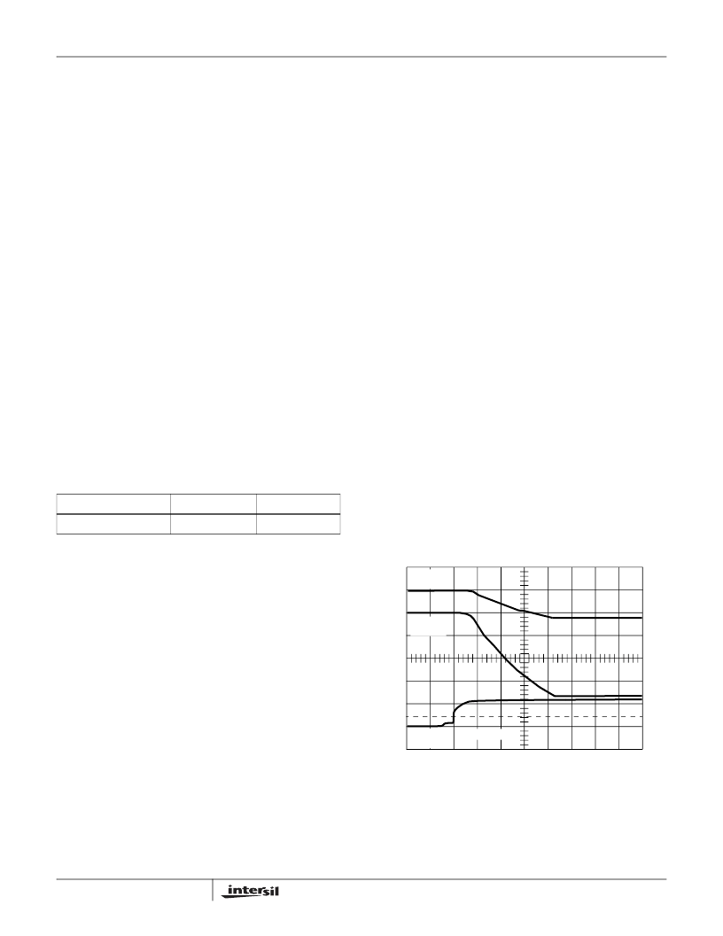
Startup
The ISL6401 features an internal digital soft start to reduce
transformer and output capacitor stress and to reduce the
inrush current surge on the input circuits. Figure 1 shows the
startup sequence.
TABLE 2. ISL6401 EVALUATION BOARD
BOARD NAME
IC
PACKAGE
ISL6401EVAL1E
ISL6401CB
14-Ld SOIC
VOUT1
20V/DIV
VOUT2
20V/DIV
VIN
10V/DIV
10ms/DIV
FIGURE 1. SOFT START WAVEFORMS (2ms/DIV)
Application Note 1082
相關(guān)PDF資料 |
PDF描述 |
|---|---|
| AN1406 | DESIGNING WITH PECL (ECL AT + 5.0) |
| AN1504 | Metastability and the ECLinPS Family |
| AN1504D | Metastability and the ECLinPS Family |
| AN1568 | Interfacing Between LVDS and ECL |
| AN1568D | Interfacing Between LVDS and ECL |
相關(guān)代理商/技術(shù)參數(shù) |
參數(shù)描述 |
|---|---|
| AN1082S | 制造商:未知廠家 制造商全稱:未知廠家 功能描述:Voltage-Feedback Operational Amplifier |
| AN1084 | 制造商:未知廠家 制造商全稱:未知廠家 功能描述:Voltage-Feedback Operational Amplifier |
| AN1084S | 制造商:未知廠家 制造商全稱:未知廠家 功能描述:Voltage-Feedback Operational Amplifier |
| AN10876 | 制造商:PHILIPS 制造商全稱:NXP Semiconductors 功能描述:GreenChip controller for LED lighting |
| AN10897 | 制造商:PHILIPS 制造商全稱:NXP Semiconductors 功能描述:A guide to designing for ESD and EMC |
發(fā)布緊急采購(gòu),3分鐘左右您將得到回復(fù)。