- 您現(xiàn)在的位置:買賣IC網(wǎng) > PDF目錄24812 > 935263912551 (NXP SEMICONDUCTORS) 1 CHANNEL(S), 400M bps, SERIAL COMM CONTROLLER, PQFP100 PDF資料下載
參數(shù)資料
| 型號(hào): | 935263912551 |
| 廠商: | NXP SEMICONDUCTORS |
| 元件分類: | 微控制器/微處理器 |
| 英文描述: | 1 CHANNEL(S), 400M bps, SERIAL COMM CONTROLLER, PQFP100 |
| 封裝: | 14 X 14 MM, 1 MM HEIGHT, PLASTIC, SOT-386-1, TQFP-100 |
| 文件頁數(shù): | 32/56頁 |
| 文件大?。?/td> | 277K |
| 代理商: | 935263912551 |
第1頁第2頁第3頁第4頁第5頁第6頁第7頁第8頁第9頁第10頁第11頁第12頁第13頁第14頁第15頁第16頁第17頁第18頁第19頁第20頁第21頁第22頁第23頁第24頁第25頁第26頁第27頁第28頁第29頁第30頁第31頁當(dāng)前第32頁第33頁第34頁第35頁第36頁第37頁第38頁第39頁第40頁第41頁第42頁第43頁第44頁第45頁第46頁第47頁第48頁第49頁第50頁第51頁第52頁第53頁第54頁第55頁第56頁

Philips Semiconductors
Preliminary specification
PDI1394L21
1394 full duplex AV link layer controller
2000 Jun 06
38
13.2.9
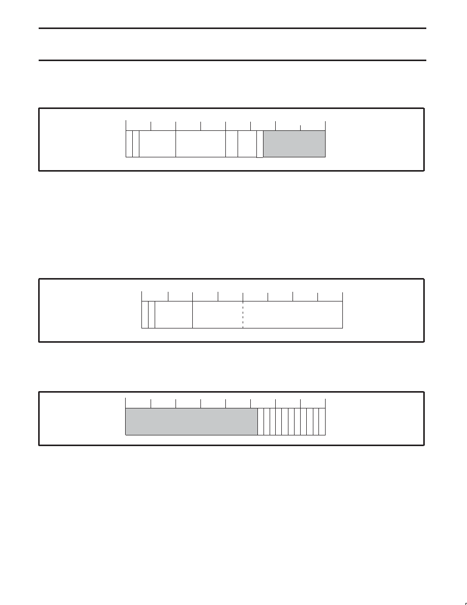
Common Isochronous Receiver Packet Header Quadlet 1 (IRXHQ1) – Base Address: 0x044
This quadlet represents the last received header value when AV receiver is operating.
29 28 27 26 25 24 23 22 21 20 19 18 17 16 15 14 13 12 11 10 9 8 7 6 5 4 3 2 1 0
SPH
QPC
FN
DBS
SV00286
E0
F0
31 30
SID
Reset Value 0x00000000
Bit 31..30:
R
E0: End of Header, F0: Format: Always set to 00 for first AV header quadlet
Bit 29..24
R
SID: Source ID, contains the node address of the sender of the isochronous data.
Bit 23.16:
R
DBS: Size of the data blocks from which AV payload is constructed. The value 0 represents a length of 256 quadlets.
Bit 15..14:
R
FN (Fraction Number): The encoding for the number of data blocks into which each source packet has been divided
(00 = 1, 01 = 2, 10 = 4, 11 = 8) by the transmitter of the packet.
Bit 13..11:
R
QPC: Number of dummy quadlets appended to each source packet before it was divided into data blocks of the
specified size.
Bit 10:
R
SPH: Indicates that a CYCTM based time stamp is inserted before each application packet (25 bits specified in the
IEC 61883 International Standard).
13.2.10
Common Isochronous Receiver Packet Header Quadlet 2 (IRXHQ2) – Base Address: 0x048
E1
F1
29 28 27 26 25 24 23 22 21 20 19 18 17 16 15 14 13 12 11 10 9 8 7 6 5 4 3 2 1 0
FMT
SYT
SV00287
31 30
FDF
Reset Value 0x0000FFFF
Bit 31..30:
R
E1: End of Header, F1: Format: Should be set to 10 for second AV header quadlet.
Bit 29..24:
R
FMT: Value inserted in the Format field.
Bit 23..0:
R
FDF/SYT: If ‘‘EN FS” in Register IRXPKCTL (0x040) is set to ‘1’, then lower 16-bits are interpreted as SYT.
13.2.11
Isochronous Receiver Interrupt Acknowledge (IRXINTACK) – Base Address: 0x04C
29 28 27 26 25 24 23 22 21 20 19 18 17 16 15 14 13 12 11 10 9 8 7 6 5 4 3 2 1 0
CIPT
AGFL
T
RCVBP
SQOV
CRCERR
IRXEMPTY
FSYNC
SEQERR
IRXFULL
SV00881
31 30
IR512LFT
IR256LFT
IR100LFT
Reset Value 0x00000000
Bit 10:
R/W
IR100LFT: Isochronous memory bank is 100 quadlets from full. (924 of 1024 quadlets in queue)
Bit 9:
R/W
IR256LFT: Isochronous data memory bank is 256 quadlets from full. (768 of 1024 quadlets are in the queue)
Bit 8:
R/W
IR512LFT: Isochronous data memory bank is 50% full. (512 of 1024 quadlets are in the queue)
Bit 7:
R/W
IRXFULL: Isochronous data memory bank has become full. This is a fatal error, the recommended action is to reset
and re-initialize the receiver.
Bit 6:
R/W
IRXEMPTY: Isochronous data memory bank has become empty.
Bit 5:
R/W
FSYNC: Pulse at fsync output.
Bit 4:
R/W
SEQERR: Sequence error of data blocks.
Bit 3:
R/W
CRCERR: CRC error in bus packet.
Bit 2:
R/W
CIPTAGFLT: Faulty CIP header tag (E,F bits). i.e.: The CIP header did not meet the standard and the whole packet
is ignored.
Bit 1:
R/W
RCVBP: Bus packet processing complete.
Bit 0:
R/W
SQOV: Status queue overflow. This is a fatal error, the recommended action is to reset and re-initialize the receiver.
相關(guān)PDF資料 |
PDF描述 |
|---|---|
| 08-1101-00 | DREHSCHALTER 1POL 12STELLUNGEN |
| 08-1260-00 | ************GESTRICHEN************ |
| 08-1341-00 | DREHSCHALTER 3POL 4STELLUNGEN |
| 08-2101-00 | DREHSCHALTER 2POL 12STELLUNGEN |
| 08-2261-00 | DREHSCHALTER 4POL 6STELLUNGEN |
相關(guān)代理商/技術(shù)參數(shù) |
參數(shù)描述 |
|---|---|
| 935264217557 | 制造商:NXP Semiconductors 功能描述:SUB ONLY IC |
| 935267356112 | 制造商:NXP Semiconductors 功能描述:IC TEA1507PN |
| 935268081112 | 制造商:NXP Semiconductors 功能描述:SUB ONLY IC |
| 935268721125 | 制造商:NXP Semiconductors 功能描述:Buffer/Line Driver 1-CH Non-Inverting 3-ST CMOS 5-Pin TSSOP T/R |
| 935269304128 | 制造商:ST-Ericsson 功能描述:IC AUDIO CODEC W/TCH SCRN 48LQFP |
發(fā)布緊急采購(gòu),3分鐘左右您將得到回復(fù)。